 Kia Optima: Disassembly
| ŌĆó |
Do not disassemble the
BJ assembly. |
| ŌĆó |
Special grease must be
applied to the driveshaft joint. Do not substitute with another
type of grease. |
| ŌĆó |
The boot band should
be replaced with a new one. |
|
| 1. |
Remove the circlip (B) from the
driveshaft spline (A).
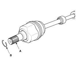
|
| 2. |
Remove both boot bands from the
transaxle side joint(TJ) case.
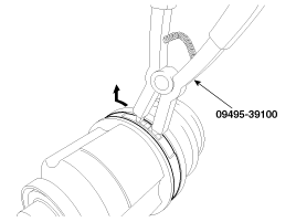
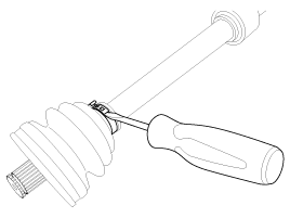
|
| 3. |
Pull out the boot from transaxle
side joint case (B). |
| 4. |
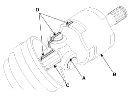
While dividing joint(TJ) boot
(A) of the transaxle side, wipe the grease in TJ case (B) and collect them
respectively.
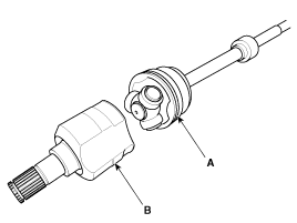
|
Make alignment marks (D) on spider roller assembly (A), joint case
(B), and shaft spline (C) to aid reassembly. |
|
| 5. |
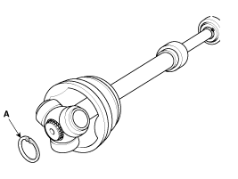
Remove the snap ring (A) from
the shaft.
|
| 6. |
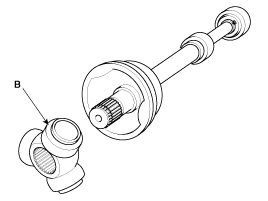
Remove the spider assembly (B)
from the driveshaft.
|
| 7. |
Clean the spider assembly. |
| 8. |
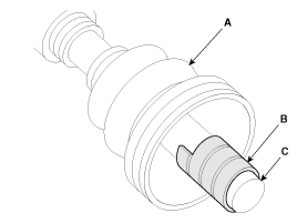
Remove the boot (A) of the transaxle
side joint(TJ).
|
For reusing the boot (A), wrap tape (B) around the driveshaft splines
(C) to protect the boot (A). |
|
| 9. |
Using a plier or flat-tipped
(-) screwdriver, remove the both side of clamp (B) of the dynamic damper
(A).
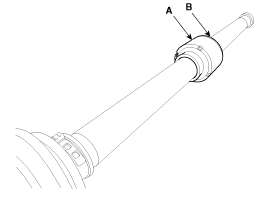
|
| 10. |
Fix the driveshaft (A) with a
vice (B) as illustrated.
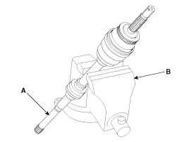
|
| 11. |
Apply soap powder on the shaft
to prevent being damaged between the shaft spline and the dynamic damper
when the dynamic damper is removed. |
| 12. |
Saperate the dynamic damper (A)
from the shaft (B) carefully.
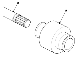
|
| 13. |
Using a plier or flat-tipped
(-) screwdriver, remove the BJ boot band on the side of wheel.
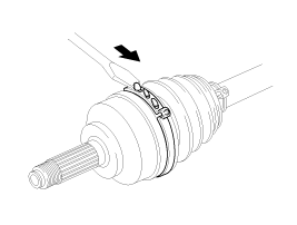
|
| 14. |
Pull out the joint (BJ) on the
side of wheel into transaxle direction.
|
Be careful not to damage the boot. |
|
1.
Check the driveshaft boots for
damage and deterioration.
2.
Check the driveshaft spline for
wear or damage.
3.
Check that there is no water
or ...
1.
Wrap tape around the driveshaft
spline(TJ) to prevent damage to the boots.
2.
Apply grease to the joint boot
on the side of the wheel and install the boot.
...
See also:
To Defog Inside Windshield
To Defog Inside Windshield
1. Select any fan speed except OFF ()
position.
2. Select desired temperature.
3. Press the defrost button ().
4. The air conditioning will be turned on according to ...
Components and Components Location
1. Piston ring
2. Snap ring
3. Piston
4. Connecting rod
5. Connecting rod upper bearing
6. Piston pin
7. Connecting rod lower bearing
8. Connecting ...
Component (1)
Connector Pin Information
No
Connector A (14P)
No
Connector B (26P)
1
GND 1
1
-
15
...
 Kia Optima: Disassembly
 Inspection
 Reassembly


