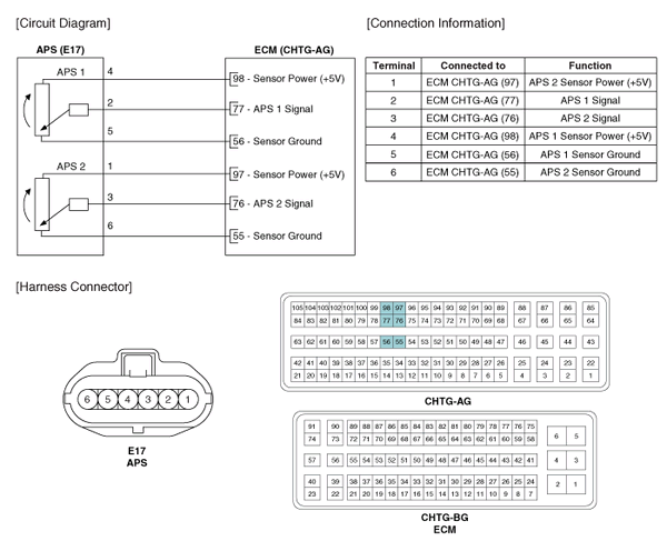
 Kia Optima: Accelerator Position Sensor (APS). Schematic Diagrams
Circuit Diagram

 Accelerator Position Sensor (APS). Specifications
Specification
Accelerator
Position
Output Voltage (V)
APS1
APS2
C.T
0.7 ~ 0.8
0.29 ~ 0.46
...
See also:
Meaning Of Symbols
There are five primary symbols used to complement illustrations. These symbols
indicate the part to apply such materials during service.
Symbol
Meaning
...
Fuses
A vehicleŌĆÖs electrical system is protected
from electrical overload damage by
fuses.
This vehicle has 2 fuse panels, one located
in the driverŌĆÖs side panel bolster, the
other in the e ...
Copyright ® www.kiopman.com 2026

