 Kia Optima: Repair
procedures
Kia Optima: Repair
procedures
Starter Circuit Troubleshooting
|
The battery must be in good condition and fully charged. |
|
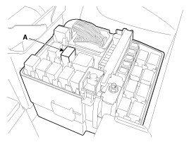
1. |
Disconnect the fuel pump relay (A) in the fuse box.
|
|
2. |
With the shift lever in N or P (A/T) or clutch pedal
pressed (M/T), turn the ignition switch to "START"
If the starter normally cranks the engine, starting
system is OK. If the starter will not crank the engine at all, go to
next step.
If it won't disengage from the ring gear when you
release key, check for the following until you find the cause.
| A. |
Solenoid plunger and switch malfunction. |
| B. |
Dirty pinion gear or damaged overrunning
clutch. |
|
|
3. |
Check the battery condition. Check electrical connections
at the battery, battery negative cable connected to the body, engine
ground cables, and the starter for looseness and corrosion. Then try
starting the engine again.
If the starter cranks normally the engine, repairing
the loose connection repaired the problem. The starting system is now
OK.
If the starter still does not crank the engine, go
to next step. |
|
4. |
Disconnect the connector from the S-terminal of solenoid.
Connect a jumper wire from the B-terminal of solenoid to the S-terminal
of solenoid.
If the starter cranks the engine, go to next step. If the starter still does not crank the engine, remove
the starter, and repair or replace as necessary. |
|
5. |
Check the following items in the order listed until
you find the open circuit.
| A. |
Check the wire and connectors between the
driver's under-dash fuse/relay box and the ignition switch,
and between the driver's under-dash fuse/relay box and the starter. |
| B. |
Check the ignition switch (Refer to BE group
- Ignition System) |
| C. |
Check the transaxle range switch connector
or ignition lock switch connector. |
| D. |
Inspect the starter relay. |
|
Starter Solenoid Test
|
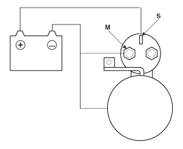
1. |
Disconnect the field coil wire from the M-terminal
of solenoid switch. |
|
2. |
Connect the battery as shown. If the starter pinion
pops out, it is working properly. To avoid damaging the starter, do
not leave the battery connected for more than 10 seconds.
|
|
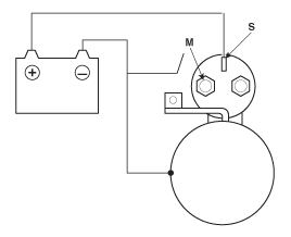
3. |
Disconnect the battery from the M terminal. If the pinion does not retract, the hold-in coil
is working properly. To avoid damaging the starter, do not leave the
battery connected for more than 10 seconds.
|
|
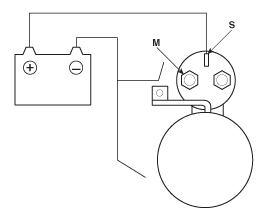
4. |
Disconnect the battery also from the body. If the
pinion retracts immediately, it is working properly. To avoid damaging
the starter, do not leave the battery connected for more than 10 seconds.
|
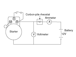
Free Running Test
|
1. |
Place the starter motor in a vise equipped with soft
jaws and connect a fully-charged 12-volt battery to starter motor as
follows. |
|
2. |
Connect a test ammeter (150-ampere scale) and carbon
pile rheostats as shown in the illustration. |
|
3. |
Connect a voltmeter (15-volt scale) across starter
motor.
|
|
4. |
Rotate carbon pile to the off position. |
|
5. |
Connect the battery cable from battery's negative
post to the starter motor body. |
|
6. |
Adjust until battery voltage shown on the voltmeter
reads 11.5volts. |
|
7. |
Confirm that the maximum amperage is within the specifications
and that the starter motor turns smoothly and freely. |
Current : 105A, MAXSpeed :
2,950 rpm, MIN
|
Description
The starting system includes the battery, starter, solenoid
switch, ignition switch, inhibitor switch (A/T), clutch pedal switch (M/T),
ignition lock switch, connection wires and th ...
See also:
Disc Brake Wear Indicators
Your vehicle has disc brakes.
When your front brake pads are worn and itŌĆÖs time for new pads, you will hear
a high-pitched warning sound from your front brakes. You may hear this sound come
and ...
Towing
If the vehicle needs to be towed, call a professional towing service. Never
tow vehicle with just a rope or chain. It is very dangerous. ...
Repair procedures
Component Replacement After Deployment
Before doing any SRS repairs, use the GDS Pro to check for DTCs. Refer to
the Diagnostic Trou ...
 Description
and Operation
Description
and Operation
