
 Kia Optima: Removal
| 1. | Disconnect the negative (-) battery terminal. |
| 2. | Remove the driver airbag module. (Refer to the RT group) |
| 3. | Remove the steering wheel. (Refer to the ST group - "Steering column & shaft") |
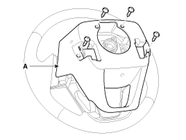
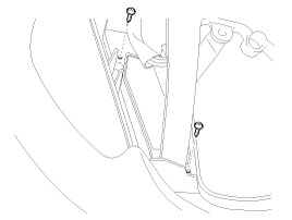
| 4. | Remove the steering wheel cover
(A) after loosening the screws.
|
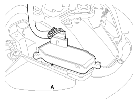
| 5. | Remove the steering wheel remote
control switch connector (A) after loosening the mounting screws. [LH-Mute]
|
 Inspection
1.
Check the audio remote control
switch for resistance between terminals in each switch position.[Trip
+ Reset]
Switch
Connector
...
 Installation
1.
Reassemble the steering wheel
remote control switch after connecting the connector.
2.
Reassemble the steering wheel.
3.
Reassemble the driver airbag
...
See also:
BCM Connector Terminals
BCM Input Signal SPEC
Signal Name
Description
Input Characteristics
(determinant condition
of connector base)
Power
Source
(Pull Up)
...
Headlight High Beam Indicator
This indicator illuminates
when the headlights are on and in the high beam position or when the turn signal
lever is pulled into the Flash-to-Pass position. ...
Rear parking assist system
The rear parking assist system assists the driver during backward movement of
the vehicle by chiming if any object is sensed within a distance of 120 cm (47 in.)
behind the vehicle. This system ...
Categories
Kia Optima Manuals
- Kia Optima DL3 2019-2026 Owners Manual
- Kia Optima DL3 2019-2026 Service and Repair Manual
- Kia Optima TF 2011-{2019} Owners Manual
- Kia Optima TF 2011-2026 Service Manual
- Kia Optima MS/Magentis 2000-2005 Owners Manual

Copyright © www.kiopman.com 2026