 Kia Optima: Removal
| 1. |
Turn ignition switch OFF and
disconnect the negative (-) battery cable. |
| 2. |
Remove the crash pad lower panel
and reinforcing panel. (Refer to the Body group- crash pad). |
| 3. |
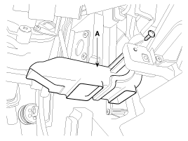
Remove the shower duct (A).

|
| 4. |
Pull down steering column shaft
after removing bolts and nuts. (Refer to the steering group - Steering columm
& shaft) |
| 5. |
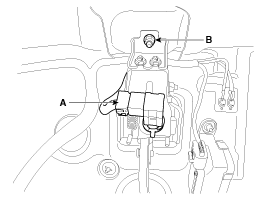
Disconnect the stop lamp switch
connector (A).

|
| 6. |
Remove the brake pedal member
mounting nut (B).
Tightening torque:9.8 ~
14.7 N.m (1.0 ~ 1.5 kgf.m, 7.2 ~ 10.8 lb-ft)
|
|
| 7. |
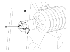
Remove the snap pin (A) and clevis
pin (B).

|
| 8. |
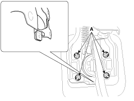
Remove the brake pedal member
assembly mounting nuts (A) and then remove the brake pedal assembly.
Tightening torque:12.7
~ 15.6 N.m (1.3 ~ 1.6 kgf.m, 9.4 ~ 11.6 lb-ft)
|

|
Push the brake booster and then remove the hook after raising the
brake pedal when removing the brake pedal assembly. |
|
1.
Check the bushing for wear.
2.
Check the brake pedal for bending
or twisting.
3.
Check the brake pedal return
spring for damage.
4.
...
 Kia Optima: Removal
 Inspection


