
 Kia Optima: Power Window Switch. Repair procedures
Inspection
Power Window Main Switch Inspection| 1. | Disconnect the negative (-) battery terminal. |
| 2. | Remove the front door trim panel. (Refer to the BD group - "Front door") |
| 3. | Disconnect the connector from
the switch.
|
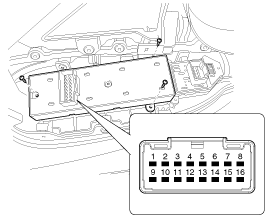
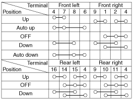
| 4. | Check for continuity between
the terminals in each switch position according to the table. If the continuity
condition is not normal, replace the switch.
|
![[Auto Down]](images/books/1609/stfbe1193n.gif)
![[Safety Up/Down]](images/books/1609/stfbe1445n.gif)
| 1. | Disconnect the negative (-) battery terminal. |
| 2. | Remove the front door trim panel. (Refer to the BD group - "Front door") |
| 3. | Disconnect the connector from
the switch.
|
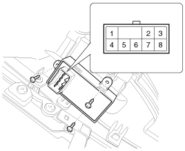
| 4. | Check for continuity between
the terminals in each switch position according to the table. If the continuity
condition is not normal, replace the switch.
|
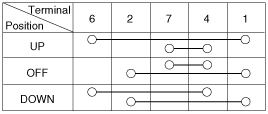
| 1. | Disconnect the negative (-) battery terminal. |
| 2. | Remove the rear door trim panel.
(Refer to the BD group - "Rear door") |
| 3. | Disconnect the 8P connector from
the switch.
|
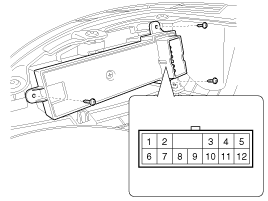
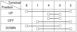
| 4. | Check for continuity between
the terminals in each switch position according to the table. If the continuity
condition is not normal, replace the switch.
|

 Power Window Relay. Repair procedures
Inspection
Diagnosis With GDS
1.
It will be able to diagnose defects
of power window with GDS quickly. GDS can operates actuator forcefully,
input/output value monitoring and self di ...
See also:
Highway driving
Tires
Adjust the tire inflation pressures to specification. Low tire inflation pressures
will result in overheating and possible failure of the tires.
Avoid using worn or damaged tires which may r ...
Using CD Player
1. CD Button
If the CD is loaded, turns to CD mode. If no CD, it displays “No Media” for 3
seconds and returns to the previous mode.
2. 1 Button (RANDOM)
Press this button for less than 0.8 ...
Components and Components Location
1. Piston ring
2. Snap ring
3. Piston
4. Connecting rod
5. Connecting rod upper bearing
6. Piston pin
7. Connecting rod lower bearing
8. Connecting ...
Categories
Kia Optima Manuals
- Kia Optima DL3 2019-2026 Owners Manual
- Kia Optima DL3 2019-2026 Service and Repair Manual
- Kia Optima TF 2011-{2019} Owners Manual
- Kia Optima TF 2011-2026 Service Manual
- Kia Optima MS/Magentis 2000-2005 Owners Manual
