 Kia Optima: Mode selection
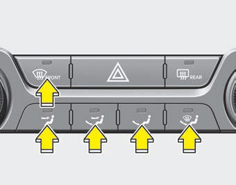
The mode selection button controls the direction of the air flow through the ventilation system
 Face-Level (B, C,
D, E, F)
Face-Level (B, C,
D, E, F)
Air flow is directed toward the upper body and face. Additionally, each outlet can be controlled to direct the air discharged from the outlet.
 Bi-Level (B, C, D,
E, F)
Bi-Level (B, C, D,
E, F)
Air flow is directed towards the face and the floor.
 Floor-Level (A, C,
D, E)
Floor-Level (A, C,
D, E)
Most of the air flow is directed to the floor, with a small amount of the air being directed to the windshield and side window defrosters.
 Floor/Defrost-Level
(A, C, D, E)
Floor/Defrost-Level
(A, C, D, E)
Most of the air flow is directed to the floor and the windshield with a small amount directed to the side window defrosters.
 Defrost-Level (A,
D)
Defrost-Level (A,
D)
Most of the air flow is directed to the windshield with a small amount of air OTF040121 directed to the side window defrosters.
 Heating and air conditioning
1. Start the engine.
2. Set the mode to the desired position. To improve the effectiveness of heating
and cooling :
- Heating: - Cooling:
3. Set the temperature control to the desired position.
...
 MAX A/C-Level (B, D, E)
To operate the MAX A/C, turn the temperature knob to extreme left. Air flow is
directed toward the upper body and face. In this mode, the air conditioning and
the recirculated air position will ...
See also:
Seat warmer (if equipped)
The seat warmer is provided to warm the front seats during cold weather. While
the engine is running, push either of the switches to warm the driver's seat or
the front passenger's sea ...
Removal
1.
Remove the mirror wiring cover
(A).
2.
Disconnect the mirror connector
(B) and remove the mounting screw (A).
3.
Slide the ...
Underdrive Brake Control Solenoid Valve(UD/B_VFS). Specifications
Specifications
Direct control VFS[35R/C]▷ Control type : Normal low type
Control Pressure kpa(kgf/cm², psi)
500.14~9.81(5.1~0.1,72.54~1.42)
Curren ...
Categories
Kia Optima Manuals
- Kia Optima DL3 2019-2026 Owners Manual
- Kia Optima DL3 2019-2026 Service and Repair Manual
- Kia Optima TF 2011-{2019} Owners Manual
- Kia Optima TF 2011-2026 Service Manual
- Kia Optima MS/Magentis 2000-2005 Owners Manual
