 Kia Optima: Inspection
Front brake disc thickness check
| 1. |
Check the brake pads for wear
and fade. |
| 2. |
Check the brake disc for damage
and cracks. |
| 3. |
Remove all rust and contamination
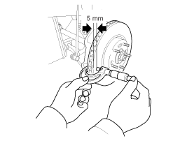
from the surface, and measure the disc thickness at 8 points, at least,
of same distance (5mm) from the brake disc outer circle.
Front brake disc thickness
- Standard: 28 mm (1.10 in)
- Service Limit: 26.4 mm (1.04 in)Deviation: Less than 0.005mm
(0.0002in)
|
|
| 4. |
If wear exceeds the limit, replace
the discs and pad assembly left and right of the vehicle. |
Front Brake Pad Check
| 1. |
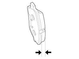
Check the pad wear. Measure the
pad thickness and replace it, if it is less than the specified value.
Pad thicknessStandard value:
11 mm (0.43 in)
Service limit: 2.0 mm (0.0787 in)
|
|
| 2. |
Check that grease is applied,
to sliding contact points. Check for metal damage to the pad and backing.
|
Front brake disc runout check
| 1. |
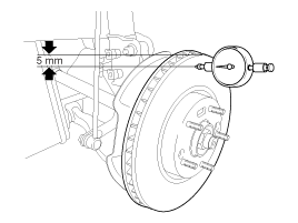
Place a dial gauge about 5mm
(0.2 in.) from the outer circumference of the brake disc, and measure the
runout of the disc.
Brake disc runoutLimit:
0.04 mm (0.0016 in.) or less (new one)
|
|
| 2. |
If the runout of the brake disc
exceeds the limit specification, replace the disc, and then measure the
runout again. |
| 3. |
If the runout does not exceed
the limit specification, install the brake disc after turning it 180° and
then check the runout of the brake disc again. |
| 4. |
If the runout cannot be corrected
by changing the position of the brake disc, replace the brake disc. |
Front brake pads
1.
Loosen the guide rod bolt (B)
and pivot the caliper (A) up out of the way.
Tightening torque:21.6
~ 31.4 N.m (2.2 ~ 3.2 kgf.m, 15.9 ~ 23.1 lb-ft)
...
1.
Installation is the reverse of
removal.
2.
Use a SST (09581-11000) when
installing the brake caliper assembly.
3.
After installation, bleed ...
See also:
Front Body B
Hood hinge mounting hole (Ø10)
Fender apron upper inner panel tooling hole (Ø6.6)
Engine mo ...
Removal
1.
Remove the shift lever knob.
(Refer to the BD group - "Console")
2.
Remove the console upper cover
(A).
3.
Disconnect the conn ...
Hazardous driving conditions
When hazardous driving conditions are encountered such as water, snow, ice, mud,
sand, or similar hazards, follow these suggestions:
Drive cautiously and allow extra distance for braking.
Avoi ...

 Replacement
 Installation