 Kia Optima: Diagnosis procedure by using diagnostic device
As manual for diagnosis methods by using diagnosis device, the main contents are as follows:
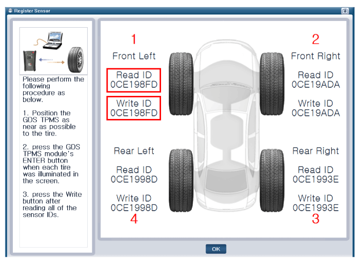
| 1. | Connect self-diagnosis connector(16pins) located in the lower of driver side crash pad to self-diagnosis device, and then turn the self-diagnosis device after key is ON. |
| 2. | Select the "vehicle model" and "TPMS" on GDS vehicle selection screen, then select OK. |
![[Register Sensor function description]](images/books/1268/stfss2001n.gif)
![[Preparation phase sensor measurements]](images/books/1268/stfss2002n.gif)
![[Sensor register method 1]](images/books/1268/stfss2003n.gif)
![[Sensor register method 2]](images/books/1268/stfss2004n.gif)
![[Sensor register method 3]](images/books/1268/stfss2005n.gif)
![[Sensor register method 4]](images/books/1268/stfss2006n.gif)
![[Sensor register method 5]](images/books/1268/stfss2007n.gif)
|
![[Sensor function description]](images/books/1268/stfss2009n.gif)
![[Preparation phase sensor measurements]](images/books/1268/stfss2010n.gif)
|
![[Sensor measurements 2]](images/books/1268/stfss2012n.gif)
![[Sensor Status]](images/books/1268/stfss2013n.gif)
|
 Installation
Sensor Fit
ŌĆó
Handle the sensor with
care.
ŌĆó
Avoid lubricant contact.
...
 TPMS Receiver. Description and Operation
Description
1.
Mode
(1)
Virgin State
A.
The receiver
as a sole part is shipped in this state. Replacement parts
should therefore arr ...
See also:
Passenger Airbag (PAB) Module. Components and Components Location
Components
...
Components (1)
1. Parking brake pedal
2. Parking brake cable
3. Equalizer assembly
4. Parking brake lever assembly
...
Replacement (With EPB)
Rear brake pads
1.
Remove the rear wheel & tire.
2.
Connect the GDS to the data link
connector located underneath the dash panel.
3.
Ignition "ON& ...
Categories
Kia Optima Manuals
- Kia Optima DL3 2019-2026 Owners Manual
- Kia Optima DL3 2019-2026 Service and Repair Manual
- Kia Optima TF 2011-{2019} Owners Manual
- Kia Optima TF 2011-2026 Service Manual
- Kia Optima MS/Magentis 2000-2005 Owners Manual

Copyright ® www.kiopman.com 2026