 Kia Optima: Installation
Sensor Fit
| ŌĆó |
Handle the sensor with
care. |
| ŌĆó |
Avoid lubricant contact. |
| ŌĆó |
Ensure that the wheel
to be fitted is designed for sensor mount. There should normally
be a mark to indicate this. |
| ŌĆó |
Ensure that the valve
hole and mating face of the wheel are clean. |
|
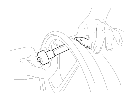
| 1. |
Slide the sensor-valve unit through
the valve hole of the rim. Hold the sensor against the rim and the rubber
grommet against the sealing surface. |
| 2. |
Insert the nut over the valve
stem and then tighten the nut.
|
| 3. |
Continue to tightening the nut
until contact with the rim and then tighten to 3.5 ~ 4.5Nm.
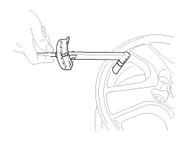
| -
|
Tighten slowly
with quarter turn steps until the final torque is reached. |
| -
|
Do not exceed
allowed torque. |
| -
|
Do not use electric
or pneumatic tools. |
|
|
| 4. |
Check that the sensor is firmly
attached to the rim.
|
Risk of damage during the tire installation/ removal if the sensor
is not firmly attached to the rim. |
|
| 5. |
Carry out inflation / pressure
correction and then fit valve cap.
|
Change the newly installed sensor mode to Normal Fixed Base(Low
Line) with the 'GDS'. Mode (Status / option) of the sensor installed
to the vehicle should be Normal Fixed Base (Low).
|
|
| 6. |
Install the tire. (Refer to "Tire
Installation") |
| 7. |
In the case of TPMS sensor failure,
TPMS sensor needs learning. Faulty sensor is replaced new units, conduct
learning of TPMS sensors. |
Repair tire after using the Tire Mobility
Kit (TMK)
When the TPMS warning lamp OFF
1.
Remove the TMK repaired tire,
wheel and TPMS sensor.(Refer to "Tire removal&quo ...
As manual for diagnosis methods by using diagnosis device, the main contents are
as follows:
1.
Connect self-diagnosis connector(16pins)
located in the lower of driver side crash pad to ...
See also:
Instrument panel illumination
The instrument panel illumination intensity can be adjusted by pressing the control
switch with the headlight switch in any position when the ignition switch is in
the ON position.
The illumina ...
One person per belt
Two people (including children) should never attempt to use a single seat belt.
This could increase the severity of injuries in case of an accident. ...
Inspection
Throttle Position Sensor (TPS)
1.
Connect the GDS on the Data Link Connector (DLC).
2.
Start the engine and measure the output voltage of
TPS 1 and 2 at C.T. and ...
 Replacement
 Diagnosis procedure by using diagnostic device