 Kia Optima: Replacement
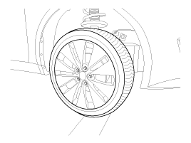
| 1. |
Loosen the wheel nuts slightly.
Raise the vehicle, and make sure it is securely supported.
|
| 2. |
Remove wheel nuts, front wheel
and tire from front hub.
Tightening torque:88.2
~ 107.8 N.m (9.0 ~ 11.0 kgf.m, 65.0 ~ 79.5 lb-ft)
|
|
Be careful not to damage to the wheel nuts when removing the front
wheel and tire. |
|
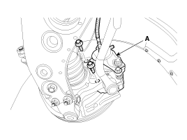
| 3. |
Remove the brake caliper mounting
bolts , and then hold the brake caliper assembly (A) with wire.
Tightening torque:78.4
~ 98.0 N.m (8.0 ~ 10.0 kgf.m, 57.8 ~ 72.3 lb-ft)
|
|
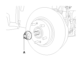
| 4. |
Remove driveshaft nut (A) from
the front hub when applying the brake.
Tightening torque:215.7
~ 254.9 N.m (22.0 ~ 26.0 kgf.m, 159.1 ~ 188.0 lb-ft)
|
|
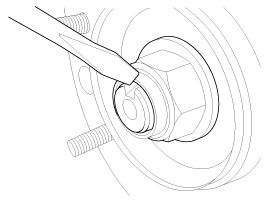
After installation lock nut, stake the lock nut using a chisel and
hammer as shown in the illustration below. |
|
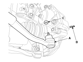
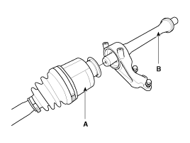
| 5. |
Remove the tie rod end ball joint
(A) from the knuckle.
| (1) |
Remove the split pin
(C). |
| (2) |
Remove the castle nut
(B).
Tightening torque:
34.3 ~ 44.0 N.m (3.5 ~ 3.4 kgf.m, 25.3 ~ 32.5 lb-ft)
|
|
|
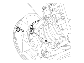
| 6. |
Loosen the mount bolt and then
remove the wheel speed sensor (A) from knuckle.
Tightening torque:6.8 ~
10.7 N.m (0.7 ~ 1.1 kgf.m, 5.0 ~ 7.9 lb-ft)
|
|
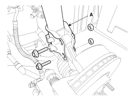
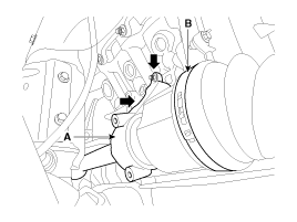
| 7. |
Loosen the bolt & nut and then
remove the knuckle from the strut assembly (A).
Tightening torque:156.9
~ 176.5N.m (16.0 ~ 18.0kgf.m, 115.7 ~ 130.2lb-ft)
|
|
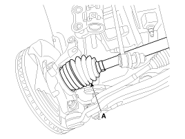
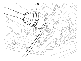
| 8. |
Disconnect the driveshaft (A)
from the front hub assembly.
|
| 9. |
Insert a pry bar between the
transaxle case and joint case, and separate the driveshaft (A) from the
transaxle case.
| ŌĆó
|
Use a pry bar
(A) being careful not to damage the transaxle and joint. |
| ŌĆó
|
Do not insert
the pry bar (A) too deep, as this may cause damage to the
oil seal. |
| ŌĆó
|
Do not pull the
driveshaft by excessive force it may cause components inside
the joint kit to dislodge resulting in a torn boot or a
damaged bearing. |
| ŌĆó
|
Plug the hole
of the transaxle case with the oil seal cap to prevent contamination. |
| ŌĆó
|
Support the driveshaft
properly. |
| ŌĆó
|
Replace the retainer
ring whenever the driveshaft is removed from the transaxle
case. |
|
|
| 10. |
Install in the reverse order
of removal. |
| 1. |
Loosen the wheel nuts slightly.
Raise the vehicle, and make sure it is securely supported.
|
| 2. |
Remove the front wheel and tire
from front hub.
Tightening torque:88.2
~ 107.8 N.m (9.0 ~ 11.0 kgf.m, 65.0 ~ 79.5 lb-ft)
|
|
Be careful not to damage to the hub bolts when removing the front
wheel and tire. |
|
| 3. |
Remove the brake caliper mounting
bolts , and then place the brake caliper assembly (A) with wire.
Tightening torque:78.4
~ 98.0 N.m (8.0 ~ 10.0 kgf.m, 57.8 ~ 72.3 lb-ft)
|
|
| 4. |
Remove the tie rod end ball joint
(A) from the knuckle.
| (1) |
Remove the split pin
(B). |
| (2) |
Remove the castle nut
(C). |
Tightening torque:34.3
~ 44.1 N.m (3.5 ~ 4.5 kgf.m, 25.3 ~ 32.5 lb-ft)
|
|
| 5. |
Loosen the mount bolt and then
remove the wheel speed sensor (B) from knuckle (A).
Tightening torque:6.8 ~
10.7 N.m (0.7 ~ 1.1 kgf.m, 5.0 ~ 7.9 lb-ft)
|
|
| 6. |
Remove driveshaft coking nut
(A) from the front hub under applying the break.
Tightening torque:196.1
~ 254.9 N.m (20.0 ~ 26.0 kgf.m, 144.6 ~ 188.0 lb-ft)
|
| ŌĆó
|
The rear hub
lock nut should be replaced with new ones. |
| ŌĆó
|
After installation
lock nut, stake the lock nut using a chisel and hammer as
shown in the illustration below. |
|
|
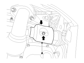
| 7. |
Remove the strut assembly (A)
from the knuckle.
Tightening torque:98.0
~ 117.6 N.m (10.0 ~ 12.0 kgf.m, 72.3 ~ 86.7 lb-ft)
|
|
| 8. |
Disconnect the driveshaft (A)
from the front hub assembly.
|
| 9. |
Remove the driveshaft cover (A).
|
| 10. |
Loosen the mounting bolts and
then remove the inner shaft (A) & driveshaft assembly (B).
|
| 11. |
Disconnect the driveshaft (A)
from inner shaft (B).
|
| 12. |
Install in the reverse order
of removal.
| ŌĆó
|
Use a pry bar
(A) being careful not to damage the transaxle and joint. |
| ŌĆó
|
Do not insert
the pry bar (A) too deep, as this may cause damage to the
oil seal. |
| ŌĆó
|
Do not pull the
driveshaft by excessive force it may cause components inside
the joint kit to dislodge resulting in a torn boot or a
damaged bearing. |
| ŌĆó
|
Plug the hole
of the transaxle case with the oil seal cap to prevent contamination. |
| ŌĆó
|
Support the driveshaft
properly. |
| ŌĆó
|
Replace the retainer
ring whenever the driveshaft is removed from the transaxle
case.
|
|
|
1.
Check the driveshaft boots for
damage and deterioration.
2.
Check the driveshaft spline for
wear or damage.
3.
Check that there is no water
or ...
See also:
Heated Oxygen Sensor (HO2S). Schematic Diagrams
Circuit Diagram
...
Installation
1.
Install the seat heater switch.
2.
Install the power window switch.
3.
Install the rear door trim.
...
Power outlet
The power outlet is designed to provide power for mobile telephones or other
devices designed to operate with vehicle electrical systems. The devices should
draw less than 10 amps with the engin ...

 Inspection