 Kia Optima: Repair procedures
Inspection
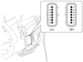
Front Door Lock Actuator Inspection| 1. | Remove the front door trim. (Refer to the BD group - "Front door") |
| 2. | Remove the front door module. |
| 3. | Disconnect the 7P connector from
the actuator.
|
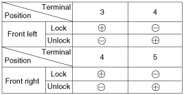
| 4. | Check actuator operation by connecting
power and ground according to the table. To prevent damage to the actuator,
apply battery voltage only momentarily.
|
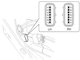
| 1. | Remove the rear door trim. (Refer to the BD group - "Rear door") |
| 2. | Remove the rear door module. |
| 3. | Disconnect the 7P connector from
the actuator.
|
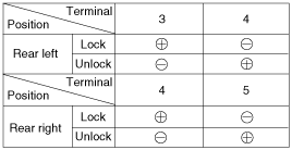
| 4. | Check actuator operation by connecting
power and ground according to the table. To prevent damage to the actuator,
apply battery voltage only momentarily.
|
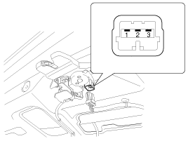
| 1. | Remove the trunk lid trim panel. (Refer to the BD group - "Trunk lid") |
| 2. | Disconnect the 3P connector from
the actuator.
|
| 3. | Check actuator operation by connecting
power and ground according to the table. To prevent damage to the actuator,
apply battery voltage only momentarily.
|
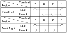
| 1. | Remove the front door trim panel. (Refer to the BD group - "Front door") |
| 2. | Remove the front door module. |
| 3. | Disconnect the 7P connector from
the actuator.
|
| 4. | Check for continuity between
the terminals in each switch position when inserting the key into the door
according to the table.
|
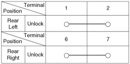
| 1. | Remove the rear door trim panel. (Refer to the BD group - "Rear door") |
| 2. | Remove the rear door module. |
| 3. | Disconnect the 7P connector from
the actuator.
|
| 4. | Check for continuity between
the terminals in each switch position according to the table.
|
| 1. | Remove the trunk lid trim. (Refer to the BD group - "Trunk lid") |
| 2. | Disconnect the 3P connector from
the actuator.
|
| 3. | Check for continuity between
the terminals in each switch position according to the table.
|
Remove the door switch and check for continuity between the terminals.
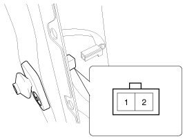

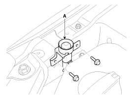
| 1. | Disconnect the connector from
the hood switch (A).
|
| 2. | Check for continuity between
the terminals and ground according to the table.
|
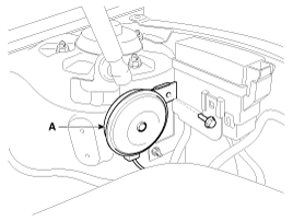
| 1. | Remove the burglar horn (A) after
removing 1 bolt and disconnect the 2P connector from the burglar horn.
|
| 2. | Test the burglar horn by connecting battery power to the terminal 1 and ground the terminal 2. |
| 3. | The burglar horn should make a sound. If the burglar horn fails to make a sound replace it. |
 Functions
DISARMCondition 1
State
Description
Initial Condition
ALARM
Event
-
IGN KEY ON during 30sec
or ALT ...
See also:
Transaxle Oil Temperature Sensor. Description and Operation
Description
Transaxle oil temperature sensor monitors the automatic transaxle fluid's temperature
and conveys the readings to TCM. It is an NTC (Negative Thermal Coefficient) sensor
whose res ...
Installation
1.
Connect the audio unit connectors
and cables.
2.
Install the audio unit.
3.
Install the center fascia upper
panel.
4.
Install the h ...
Installation
ŌĆó
Install the component with the specified
torques.
ŌĆó
Note that internal d ...

