 Kia Optima: Removal
| 1. | Disconnect the negative (-) battery terminal. |
| 2. | Remove the driver crash pad lower
panel. (Refer to the BD group - "Crash pad") |
| 3. | Remove the steering column upper
and lower shrouds. (Refer to the BD group - "Crash pad") |
| 4. | Remove the wiper switch. (Refer to the BE group - "Multifunction switch") |
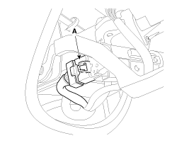
| 5. | Remove the ignition switch after
disconnecting the ignition switch 6P connector (A)
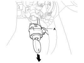
|
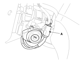
| 6. | Remove the key warning/immobilizer
connector (A).
|
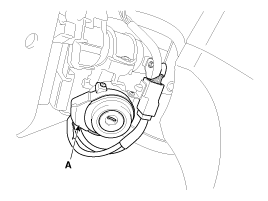
| 7. | After loosening the screw, remove
the key warning switch and key Illumination (A).
|
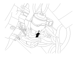
| 8. | Pushing lock pin with key ACC.
|
| 9. | Remove the key lock cylinder
(A).
|
 Installation
1.
Install the key lock cylinder.
2.
Install the key warning switch
and key Illumination.
3.
Install the key warning/immobilizer
connector.
...
See also:
Speedometer
Type A
Type B
The speedometer indicates the forward speed of the vehicle.
The speedometer is calibrated in kilometers per hour and/or miles per hour. ...
Inspection
1.
Troubleshooting for Speaker
(1)
Basic inspection of speaker
Inspect the sound from speaker after verifying that the speaker
mounting screws are removed and the w ...
Cleaning the Lap/Shoulder Belt Webbing
Clean the belt webbing with any mild soap solution recommended for cleaning upholstery
or carpet. Follow the instructions provided with the soap. Do not bleach or re-dye
the webbing because this m ...

