 Kia Optima: Removal
| 1. |
Remove the battery and the battery
tray. (Refer to "Charging system" in EE group.) |
| 2. |
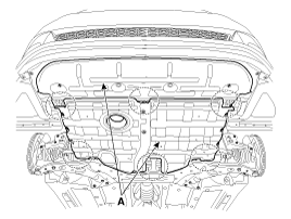
Remove the under cover (A).
Tightening torque:7.8 ~
11.8 N.m (0.8 ~ 1.2 kgf.m, 5.8 ~ 8.7 lb-ft)
|
|
| 3. |
Replace new gasket and the plug
after draining the automatic transaxle fluid by removing the drain plug.
(Refer to "Hydraulic system (Fluid)" in this group) |
| 4. |
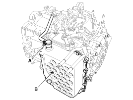
Remove the valve body cover (B)
and eyebolt (A).
Tightening torque:(A) 34.3
~ 44.1 N.m (3.5 ~ 4.5 kgf.m, 25.3 ~ 32.6 lb-ft)
(B) 13.8 ~ 14.7 N.m (1.3 ~ 1.5 kgf.m, 9.4 ~ 10.8 lb-ft)
|
|
Always replace the gasket of the eyebolt use new one whenever loosening
eyebolt. |
|
Remove installation bolts in the engine compartmentfirst and then
remove others under the vehicle |
|
| 5. |
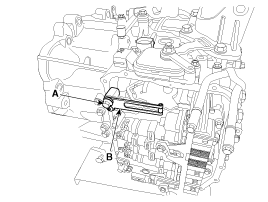
Remove the plate and the detent
spring (A) after removing the bolt.
Tightening torque:24.5
~ 35.3 N.m (2.5 ~ 3.6 kgf.m, 18.1 ~ 26.0 lb-ft)
|
|
| 6. |
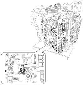
Remove the bolt (3ea) after disconnecting
the solenoid valve connector (A) and the oil temperature sensor connector
(B).
Tightening torque:9.8 ~
11.8 N.m (1.0 ~ 1.2 kgf.m, 7.2 ~ 8.7 lb-ft)
|
|
Be careful not to damage the harness lock connector. |
|
| 7. |
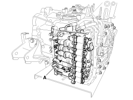
Remove the valve body assembly
(A).
Tightening torque:9.8 ~
11.8 N.m (1.0 ~ 1.2 kgf.m, 7.2 ~ 8.7 lb-ft)
|
|
| 8. |
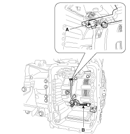
Disconnect the input & output
speed sensor connector(A). |
| 9. |
Remove the input & output speed
sensor (B) after removing the bolts(2ea).
Tightening torque:9.8 ~
11.8 N.m (1.0 ~ 1.2 kgf.m, 7.2 ~ 8.7 lb-ft)
|
|
1.
Check signal waveform of Input
& output speed sensor using the GDS.
Specification: Refer to "Signal
Wave Form" section.
...
1.
Installation is the reverse of
removal.
After replacement or reinstallation procedure of the valve body assembly, ...
See also:
Before Starting
Close and lock all doors.
Position the seat so that all controls are easily reached.
Adjust the inside and outside rearview mirrors.
Be sure that all lights work.
Check all gauges.
Check ...
Inspection
Brake Booster
1.
Inspect the check valve in the
vacuum hose, intensifier and the connecting section.
...
Intake Actuator. Description and Operation
Description
1.
The intake actuator is located
at the blower unit.
2.
It regulates the intake door
by signal from control unit.
3.
Pressing the intake ...



 Inspection
 Installation