 Kia Optima: Installation
| 1. |
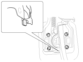
Install the brake pedal assembly
in dash panel.
|
| 2. |
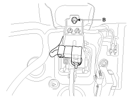
Pre-tighten the bracket fixing
bolt(B) in dash panel.
|
| 3. |
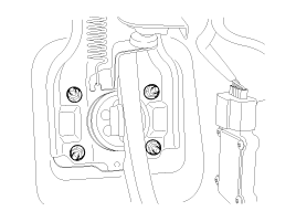
Install the brake booster and
brake pedal member fixing nut securely.
Tightening torque:12.7
~ 15.7 N.m (1.3 ~ 1.6 kgf.m, 9.4 ~ 11.6 lb-ft)
|
|
| 4. |
Tighten the bolt (B) securely
in dash panel.
Tightening torque:9.8 ~
14.7 N.m (1.0 ~ 1.5 kgf.m, 7.2 ~ 10.8 lb-ft)
|

|
| 5. |
Install the snap pin (A) and
clevis pin (B).

| ŌĆó
|
Before installing
the pin, apply the grease to the clevis pin. |
| ŌĆó
|
Use a new snap
pin whenever installing. |
|
|
| 6. |
Install the stop lamp switch
securely. |
| 7. |
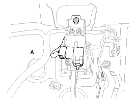
Connect the stop lamp switch
connector (A).
|
| 8. |
Adjust the brake pedal height
and free play. |
| 9. |
Check the brake pedal operation
after installing the brake pedal. |
| 10. |
Install the steering column shaft
assembly. |
| 11. |
Install the shower duct (A).
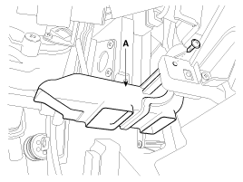
|
| 12. |
Install the reinforcing panel
and crash pad lower panel. |
| 13. |
Reconnect the battery negative
cable. |
Stop lamp switch clearance adjustment
If the gap between stop lamp switch and bracket is not 1.0 ~ 2.0mm(0.04~ 0.08in),
conform to below.
1.
Disconnect the stop lamp switch
...
Components
1. Guide rod bolt
2. Bleed screw
3. Caliper carrier
4. Caliper body
5. Inner pad shim
6. Brake pad
7. Pad retainer
...
See also:
Adjustment
Parking Brake Shoe Clearance Adjustment
1.
Raise the vehicle, and make sure
it is securely supported.
2.
Remove the rear tire and wheel.
3.
Remove the plug ...
Components
1. Roof trim
2. Sunvisor
3. Retainer
4. Assist handle bracket
...
Output Speed Sensor. Specifications
Specifications
▷ Type: Hall effect sensor
Operation condition [┬░C(┬░F)]
((-)40~150)) -40~302
Air gap(mm)in.
(0.55~1) 0.0217~0.0394
...
 Kia Optima: Installation
 Adjustment
 Front Disc Brake. Components and Components Location


