 Kia Optima: EPB connector input/output
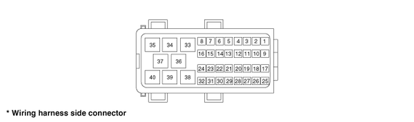
|
Pin No. |
Function |
Pin No. |
Function |
|
1 |
- |
21 |
Gear switch |
|
2 |
- |
22 |
- |
|
3 |
- |
23 |
CAN_Low |
|
4 |
- |
24 |
CAN_High |
|
5 |
- |
25 |
EPB switch 1 |
|
6 |
- |
26 |
EPB switch 2 |
|
7 |
- |
27 |
EPB switch 3 |
|
8 |
- |
28 |
EPB switch 4 |
|
9 |
- |
29 |
- |
|
10 |
- |
30 |
- |
|
11 |
- |
31 |
- |
|
12 |
- |
32 |
- |
|
13 |
- |
33 |
ground |
|
14 |
- |
34 |
ground |
|
15 |
- |
35 |
Rear right caliper motor + |
|
16 |
- |
36 |
Rear left caliper motor - |
|
17 |
Ignition 1 |
37 |
Rear right caliper motor - |
|
18 |
Key in switch |
38 |
Rear left caliper motor + |
|
19 |
- |
39 |
Rear left motor power |
|
20 |
Brake light switch] |
40 |
Rear right motor power |


See also:
Components(1)
1. Front bumper cover
2. Front bumper upper strip assembly
3. Radiator grill upper cover
4. Front bumper lower stiffner
5. Front bumper rail assembly
6. Front bum ...
Fuel Pressure Test
1.
Release the residual pressure in fuel line (Refer
to ŌĆ£Release Residual Pressure in Fuel LineŌĆØ in this group).
...
Homelink Programming
CAUTION
Make sure people and/or objects are out of the way of any garage doors or
gates you may be operating during the programming procedures.
Keep original transmitters for potential f ...
Categories
Kia Optima Manuals
- Kia Optima DL3 2019-2026 Owners Manual
- Kia Optima DL3 2019-2026 Service and Repair Manual
- Kia Optima TF 2011-{2019} Owners Manual
- Kia Optima TF 2011-2026 Service Manual
- Kia Optima MS/Magentis 2000-2005 Owners Manual

Copyright ® www.kiopman.com 2026