 Kia Optima: EPB Circuit Diagram (2)
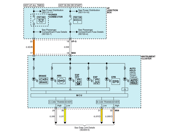

 EPB connector input/output
Pin No.
Function
Pin No.
Function
1
-
21
Gear switch
2
-
22
...
See also:
Checking the brake/clutch* fluid
level
Check the fluid level in the reservoir periodically.
The fluid level should be
between MAX and MIN marks on the
side of the reservoir.
Before removing the reservoir cap and
adding brake/c ...
Installation
1.
Installation is the reverse of
removal.
Use a new washer (A) whenever installing.
...
Removal
1.
Remove the battery and the battery
tray. (Refer to "Charging system" in EE group.)
2.
Remove the under cover (A).
Tightening torque:7.8 ~
11 ...
Categories
Kia Optima Manuals
- Kia Optima DL3 2019-2026 Owners Manual
- Kia Optima DL3 2019-2026 Service and Repair Manual
- Kia Optima TF 2011-{2019} Owners Manual
- Kia Optima TF 2011-2026 Service Manual
- Kia Optima MS/Magentis 2000-2005 Owners Manual

Copyright ® www.kiopman.com 2026