 Kia Optima: ECM Problem Inspection Procedure
| 1. |
TEST ECM GROUND CIRCUIT: Measure resistance between
ECM and chassis ground using the backside of ECM harness connector as
ECM side check point. If the problem is found, repair it.
|
| 2. |
TEST ECM CONNECTOR: Disconnect the ECM connector
and visually check the ground terminals on ECM side and harness side
for bent pins or poor contact pressure. If the problem is found, repair
it. |
| 3. |
If problem is not found in Step 1 and 2, the ECM
could be faulty. If so, make sure there were no DTC's before swapping
the ECM with a new one, and then check the vehicle again. If DTC's were
found, examine this first before swapping ECM. |
| 4. |
RE-TEST THE ORIGINAL ECM: Install the original ECM
(may be broken) into a known-good vehicle and check the vehicle. If
the problem occurs again, replace the original ECM with a new one. If
problem does not occur, this is intermittent problem (Refer to ŌĆ£Intermittent
Problem Inspection ProcedureŌĆØ in Basic Inspection Procedure).
|
VIN Programming Procedure
VIN (Vehicle Identification Number) is a number that has
the vehicle's information (Maker, Vehicle Type, Vehicle Line/Series, Body Type,
Engine Type, Transmission Type, Model Year, Plant Location and so forth. For
more information, please refer to the group "GI" in this SERVICE MANUAL). When
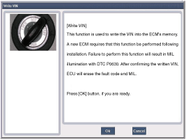
replacing an ECM, the VIN must be programmed in the ECM. If there is no VIN
in ECM memory, the fault code (DTC P0630) is set.
|
The programmed VIN cannot be changed. When writing
the VIN, confirm the VIN carefully
|
| 1. |
Select "VIN Writing" function in "Vehicle S/W Management". |
| 2. |
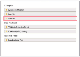
Select "Write VIN" in "ID Register". 
|
| 3. |
Input the VIN.
|
Before inputing the VIN, confirm the VIN
again because the programmed VIN cannot be changed. |

|
| 4. |
Turn the ignition switch OFF, then back ON. |
In the case of the vehicle equipped with immobilizer
or button engine start system, perform "Key Teaching" procedure together
...
See also:
Radial-ply tires
Radial-ply tires provide improved
tread life, road hazard resistance and
smoother high speed ride. The radial-
ply tires used on this vehicle are of
belted construction, and are selected
to ...
Replacement
1.
Remove the rear wheel & tire.
Tightening torque:88.3
~ 107.9N.m (9.0 ~ 11.0kgf.m, 65.1 ~ 79.6lb-ft)
...
Inspection
Smart Key Unit
-
Refer to the BE group - inspection
/ self diagnosis with GDS.
Smart Key Switch
-
Refer to the BE group - inspection
/ self diagnosis with GDS.
...
 Kia Optima: ECM Problem Inspection Procedure
 Installation


