 Kia Optima: Components

|
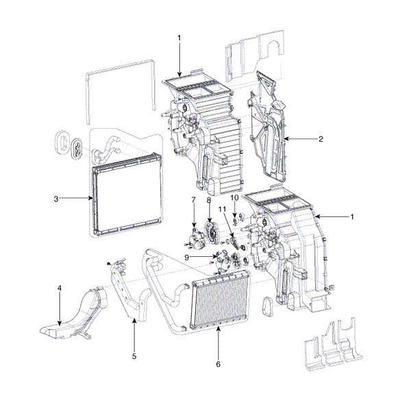
1. Heater Case (LH) 2. Separator 3. Evaporator Core 4. Shower Duct |
5. Heater Core Cover 6. Heater Core 7. Mode Actuator 8. Mode Cam |
9. Temp Actuator 10. Vent Door Arm 11. Floor Door Arm |

|
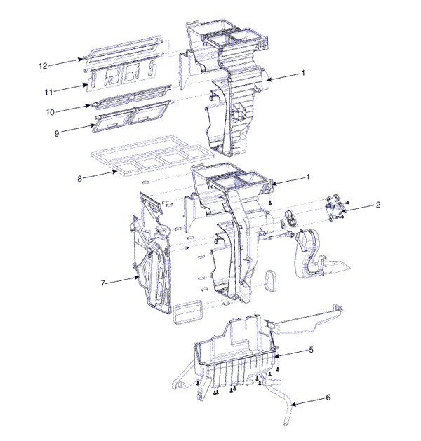
1. Heater Case (RH) 2. Temp Actuator (PA) 3. Temp Door Lever 4. Evaporator Temp Sensor |
5. Hearer Lower Caver 6. Drain Hose 7. Separator 8. Insulator |
9. Temp Control Door 10. Floor Door 11. Vent Door 12. Def Door |
 Heater Unit. Repair procedures
Replacement
1.
Disconnect the negative (-) battery
terminal.
2.
Recover the refrigerant with
a recovery/ recycling/ charging station.
3.
When the e ...
See also:
Components and Components Location
Components
1. HECU module
2. Front wheel speed sensor
3. Rear wheel speed sensor
4. Yaw rate & Lateral G sensor
5. Steering angle sensor
6. ABS Warning lamp
...
Rear safety belts
Two kinds of belts are provided:
Lap/shoulder belts for people who sit on the outboard sides of the rear
seat.
A lap belt for people who sit in the center of the rear seat.
Rear Lap/Should ...
Starting the Engine
1. Make sure the parking brake is applied.
2. Manual Transmission - Depress the clutch pedal fully and shift the transmission
into Neutral. Keep the clutch pedal depressed while turning the ignitio ...
Copyright ® www.kiopman.com 2026

