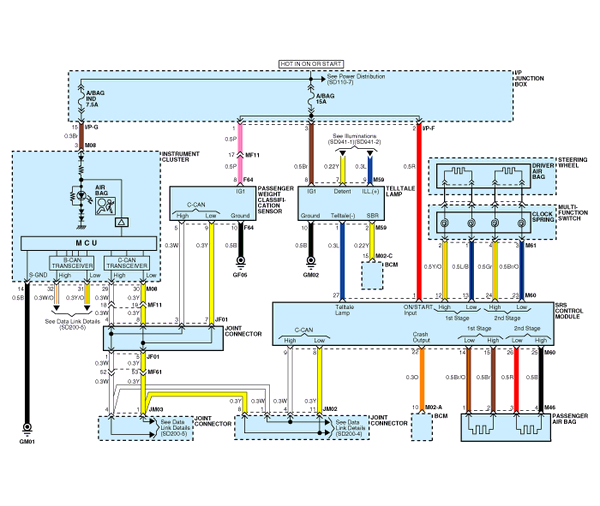
 Kia Optima: Circuit Diagram (1)

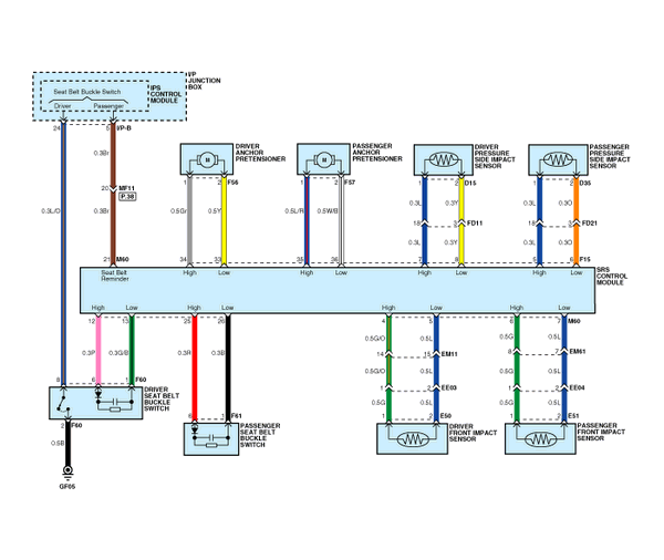
| Circuit Diagram (2) |

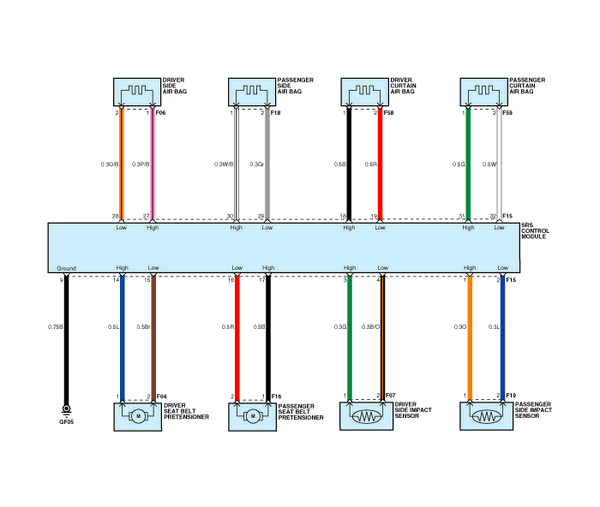
| Circuit Diagram (3) |

 SRSCM Connector Terminal
Pin
Function (Connector A)
Pin
Function (Connector A)
1
Ignition
1
Side impact sensor [Passenger] ...
See also:
All season tires
Kia specifies all season tires on
some models to provide good performance
for use all year round,
including snowy and icy road conditions.
All season tires are identified
by ALL SEASON and/o ...
Description and Operation
Refrigeration Cycle
...
Tightening Torques
Engine Control System
Item
kgf.m
N.m
lb-ft
ECM installation bolt
1.0 ~ 1.2
9.8 ~ 11.8
7.2 ~ 8.7
...
Copyright ® www.kiopman.com 2026

