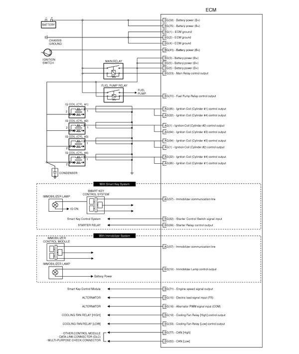
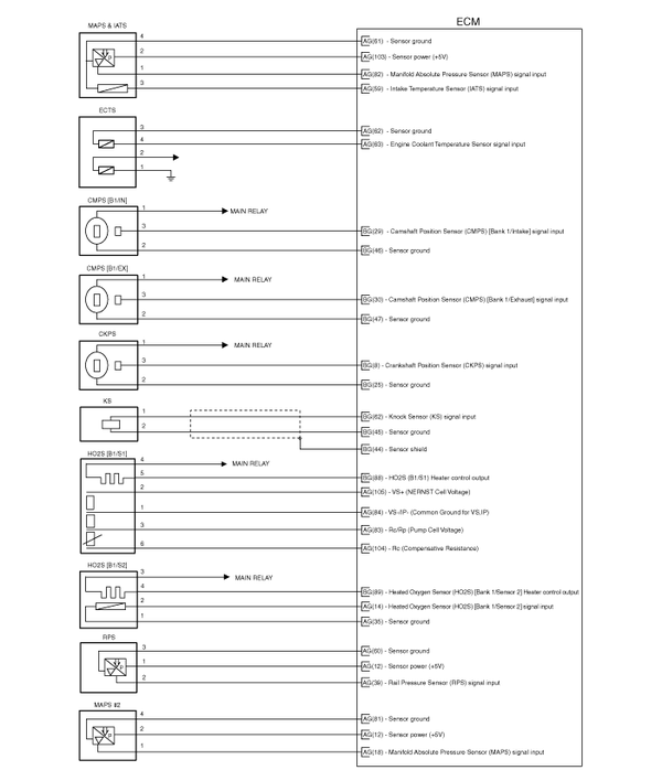
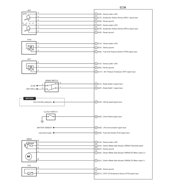
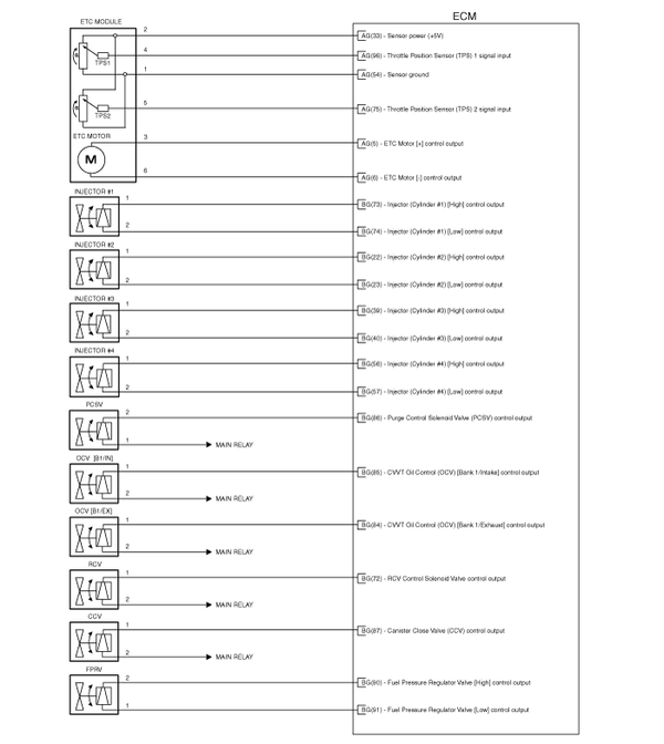
 Kia Optima: Circuit Diagram


 ECM Terminal And Input/Output signal
ECM Terminal Function
Connector [CHTG-AG]
Pin
No.
Description
Connected to
1
Ignition Coil (Cylinder #2) control output [W ...
See also:
Removal
In the case of the vehicle equipped with immobilizer
or button engine start system, perform "Key Teaching" procedure together
...
Troubleshooting
Troubleshooting
Symptom
Suspect area
Engine will not start or struggle to start
Vapor hose damaged or disconnected
Engine struggle ...
Sliding the sunroof
When the sunshade is closed
If you pull the sunroof control lever backward to the second detent position,
the sunshade will slide all the way open then the sunroof glass will slide all the
way ...
Copyright ® www.kiopman.com 2026

