 Kia Optima: Components and Components Location
Components
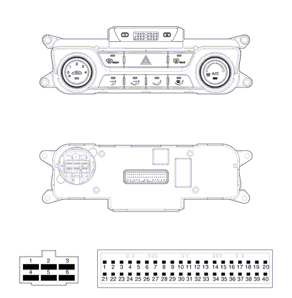
|
Connector |
PIN NO. |
Function |
Connector |
PIN No. |
Function |
|
Connector(A) |
1 |
GND |
Connector(B) |
18 |
Hazard Signal |
|
2 |
Middle High |
19 |
- |
||
|
3 |
Middle Low |
20 |
Rheostat (ILL -) |
||
|
4 |
High |
21 |
IGN2 |
||
|
5 |
Common |
22 |
IGN1 |
||
|
6 |
Low |
23 |
ACC |
||
|
Connector(B) |
1 |
BAttery |
24 |
- |
|
|
2 |
Tail Lamp (ILL+) |
25 |
- |
||
|
3 |
Sensor REF (+5V) |
26 |
Rear Defog S/W |
||
|
4 |
Mode Actuator (F/B) |
27 |
- |
||
|
5 |
Temp Actuator (F/B) |
28 |
- |
||
|
6 |
Intake Actuator (F/B) |
29 |
Detent Out (+) |
||
|
7 |
Evaporator Sensor (+) |
30 |
Blower F/B |
||
|
8 |
Ambient Sensor (+) |
31 |
Sensor GND |
||
|
9 |
- |
32 |
- |
||
|
10 |
Blower Common |
33 |
C ŌĆō Can HIGH |
||
|
11 |
HTD |
34 |
C ŌĆō Can LOW |
||
|
12 |
Mode Actuator (VENT) |
35 |
ECV + |
||
|
13 |
Mode Actuator (DEF) |
36 |
ECV ŌĆō (GND) |
||
|
14 |
Temp Actuator (COOL) |
37 |
- |
||
|
15 |
Temp Actuator (WARM) |
38 |
Sensor GND |
||
|
16 |
Intake Actuator (FRE) |
39 |
GND |
||
|
17 |
Intake Actuator (REC) |
40 |
GND |

 Heater & A/C Control Unit(Manual). Repair procedures
Replacement
1.
Disconnect the negative (-) battery
terminal.
2.
Using the screwdriver, remove
the side cover (A).
3.
Loosen the mounting scre ...
See also:
Components [Panoramaroof]
1. Roof trim
2. Sunvisor
3. Retainer
4. Assist handle bracket
...
Removal
Replacing an on/off solenoid valve (SS-A, SS-B) does not require additional
hydraulic pressure adjustment; however, the hydraulic pre ...
Fan speed control
The ignition switch must be in the ON position for fan operation.
The fan speed control knob allows you to control the fan speed of the air flowing
from the ventilation system. To change the fan ...
Categories
Kia Optima Manuals
- Kia Optima DL3 2019-2026 Owners Manual
- Kia Optima DL3 2019-2026 Service and Repair Manual
- Kia Optima TF 2011-{2019} Owners Manual
- Kia Optima TF 2011-2026 Service Manual
- Kia Optima MS/Magentis 2000-2005 Owners Manual

Copyright ® www.kiopman.com 2026