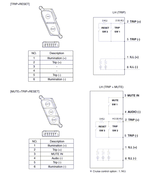
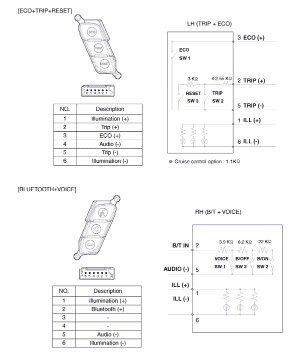
 Kia Optima: Trip Switch. Schematic Diagrams
Circuit Diagram


 Installation
1.
Install the cluster to the cluster
housing.
2.
Install the cluster fascia panel
and crash pad side garnish [LH].
3.
Install the crash pad lower pan ...
See also:
Side Airbag
Your vehicle is equipped with a side airbag in each front seat. The purpose of
the airbag is to provide the vehicleŌĆÖs driver and/or the front passenger with additional
protection other than th ...
Headrest
The rear seat(s) is equipped with headrests in the outboard seating positions
for the occupant's safety and comfort.
The headrest not only provides comfort for passengers, but also helps prot ...
ENGINE START/STOP button position
OFF
Not illuminated
ŌĆó With automatic transaxle
To turn off the engine (START/RUN position) or vehicle power (ON position), press
the ENGINE START/STOP button with the shift lever in the P (Pa ...
Copyright ® www.kiopman.com 2026

