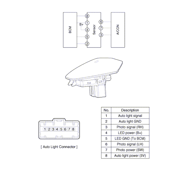
 Kia Optima: Schematic Diagrams
Circuit Diagram

 Components and Components Location
Component Location
1. Auto light sensor
2. Head lamps
3. Lighting switch (Auto)
4. Tail lamps
5. Body control module (BCM)
...
 Auto Light Switch. Repair procedures
Inspection
Lighting Switch InspectionWith the multi function switch in each position, make
sure that continuity exists between the terminals below. If continuity is not as
specified, replace the ...
See also:
Tightening Torque
Items
N.m
Kgf.m
lb-ft
Front and rear doors
Door hinge to body
34.3 ~ 41.2
3.5 ~ 4.2
25.3 ~ 30.4 ...
If the engine doesn't turn over or
turns over slowly
1. If your vehicle has an automatic
transaxle, be sure the shift lever is in N
(Neutral) or P (Park) and the emergency
brake is set.
2. Check the battery connections to be
sure they are clean ...
Alternator. Components and Components Location
Components
1. Pulley
2. Front bracket
3. Front bearing
4. Bearing cover
5. Bearing cover bolt
6. Rotor
7. Rear bearing
8. Rear bracket
9. Through bol ...
Copyright ® www.kiopman.com 2026
