 Kia Optima: Schematic Diagrams
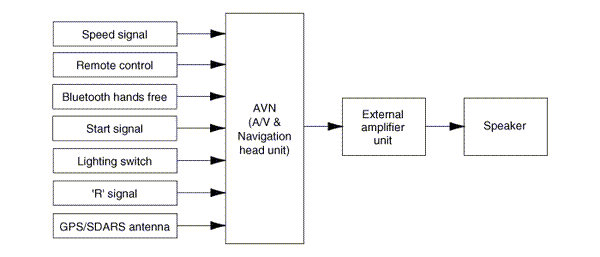
System Block Diagram
 Components and Components Location
Components Location
1. AVN (A/V & Navigation head unit)
2. Midrange speaker
3. External amplifier
4. Roof antenna (GPS + SDARS)
5. Front door speaker
6. Rear speak ...
 Description and Operation
Limitations Of The Navigation system
GPS Signal Reception StateAs the GPS satellite frequency is received/transmitted
in straight lines, reception may not work if hiding devices are placed on or ne ...
See also:
Checking the Coolant Level
WARNING - Removing Radiator Cap
Never attempt to remove the radiator cap while the engine is operating.
Doing so might lead to cooling system and engine damage and could result in
serio ...
Removal
1.
Remove the battery and the battery
tray. (Refer to "Charging system" in EE group.)
2.
Remove the under cover (A).
Tightening torque:7.8 ~
11 ...
Components
1. Roof trim
2. Sunvisor
3. Retainer
4. Assist handle bracket
...
Categories
Kia Optima Manuals
- Kia Optima DL3 2019-2026 Owners Manual
- Kia Optima DL3 2019-2026 Service and Repair Manual
- Kia Optima TF 2011-{2019} Owners Manual
- Kia Optima TF 2011-2026 Service Manual
- Kia Optima MS/Magentis 2000-2005 Owners Manual

Copyright ® www.kiopman.com 2026