 Kia Optima: Replacement
| 1. | Disconnect the negative (-) battery terminal. |
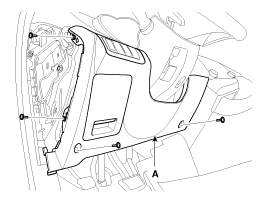
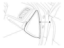
| 2. | Using the screwdriver, remove
the side cover (A).
|
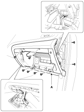
| 3. | Loosen the mounting screws and
then remove the crash pad lower cover (A)
|
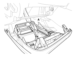
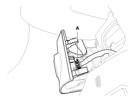
| 4. | Disconnect the connector (A),
and then remove the crash pad lower cover.
|
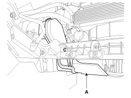
| 5. | Remove the shower duct (A).
|
| 6. | Loosen the mounting bolts and
then remove the BCM. (Refer to BE group - ŌĆ£BCMŌĆØ) |
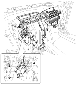
| 7. | Disconnect the temperature control actuator connector (A) |
| 8. | Loosen the mounting screw and
then remove the temperature control actuator (B).
|
| 9. | Using the screw driver, remove
the side cover (A).
|
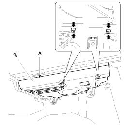
| 10. | Remove the main crash pad lower
cover (A).
|
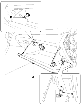
| 11. | Disconnect the damper (B) and
glove box lift (C) from the glove box (A).
|
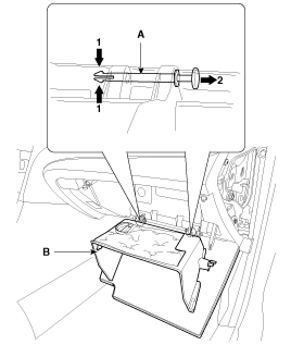
| 12. | Disconnect the pin (A) and then
remove the glove box (B).
|
| 13. | Loosen the mounting screw and
bolts and than remove the glove box housing (A).
|
| 14. | Remove the shower duct (A).
|
| 15. | . Disconnect the temperature control actuator connector (A). |
| 16. | Loosen the mounting screw and
then remove the temperature control actuator (B).
|
| 17. | Installation is the reverse order of removal. |
 Inspection
1.
Ignition "OFF"
2.
Disconnect the connector of temperature
control actuator.
3.
Verify that the temperature control
actuator operates to t ...
 Mode Control Actuator. Components and Components Location
Component Location
...
See also:
Auto Head Lamp Leveling Unit. Schematic Diagrams
Circuit Diagram
...
Component (1)
Connector Pin Information
No
Connector A (14P)
No
Connector B (26P)
1
GND 1
1
-
15
...
Removal
1.
Disconnect the negative (-) battery
terminal.
2.
Remove the front wheel guard
clip(2EA).(Refer to the BD group - "Front bumper")
3.
D ...
Copyright ® www.kiopman.com 2026


