 Kia Optima: Replacement
| 1. |
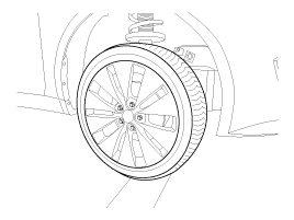
Remove the front wheel & tire.
Tightening torque:88.3
~ 107.9N.m(9.0 ~ 11.0kgf.m, 65.1~79.6lb-ft)
|
|
Be careful not to damage to the hub bolts when removing the front
wheel & tire. |
|
| 2. |
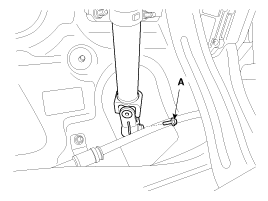
Loosen the bolt (A) and then
disconnect the universal joint assembly from the pinion of the steering
gear box.
Tightening torque:29.4
~ 34.3N.m(3.0 ~ 3.5kgf.m, 21.7 ~ 25.7lb-ft)
|
|
Lock the steering wheel in the straight ahead position to prevent
the damage of the clock spring inner cable when you handle the steering
wheel. |
|
| 3. |
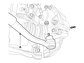
Remove the split pin and castle
nut and then disconnect the tie-rod end (A) from the front knuckle.
Tightening torque:34.3
~ 44.1N.m(3.5 ~ 4.5kgf.m, 25.7 ~ 32.5lb-ft)
|
|
| 4. |
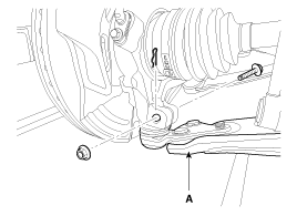
Loosen the bolt & nut and then
remove the lower arm (A).
Tightening torque:98.1
~ 117.7N.m(10.0 ~ 12.0kgf.m, 72.3 ~ 86.8lb-ft)
|
|
| 5. |
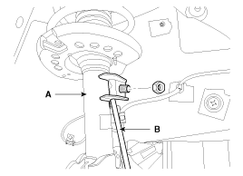
Disconnect the stabilizer link
(B) from the front strut assembly (A) after loosening the nut.
Tightening torque:98.1
~ 117.7N.m(10.0 ~ 12.0kgf.m, 72.3 ~ 86.8lb-ft)
|
|
| 6. |
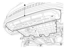
Remove the undercover (A).
|
| 7. |
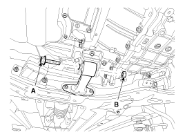
Loosen the bolt (A) & nut (B)
and then remove the roll rod stopper.
Tightening torque:107.9
~ 127.5N.m(11.0 ~ 13.0kgf.m, 79.6 ~ 94.0lb-ft)
|
|
| 8. |
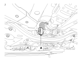
Disconnect the muffler rubber
hanger (A).
|
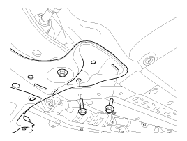
| 9. |
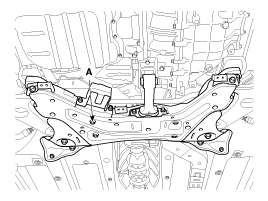
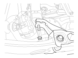
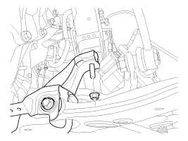
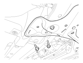
Loosen the bolts & nuts and then
remove the sub frame (A).
Tightening torqueSub frame
mounting bolts & nuts:
156.9 ~ 176.5N.m (16.0 ~ 18.0kgf.m, 115.7 ~ 130.2lb-ft)Sub frame
stay bolts & nuts:
44.1 ~ 58.8N.m (4.5 ~ 6.0kgf.m, 32.5 ~ 43.4lb-ft)
|
|
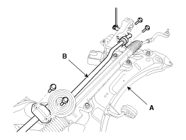
| 10. |
Loosen the mounting bolt and
then remove the stabilizer bar (B) from the sub frame(A).
Tightening torque:44.1
~ 53.9N.m(4.5 ~ 5.5kgf.m, 32.5 ~ 39.8lb-ft)
|
|
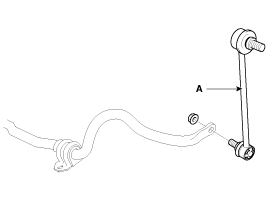
| 11. |
Loosen the nut and then remove
the stabilizer link (A) from the stabilizer bar.
Tightening torque:98.1
~ 117.7N.m(10.0 ~ 12.0kgf.m, 72.3 ~ 86.8lb-ft)
|
|
| 12. |
Installation is the reverse of
removal. |
1.
Check the bushing for wear and
deterioration.
2.
Check the front stabilizer bar
for deformation.
3.
Check the front stabilizer link
ball joint ...
See also:
Cylinder Head. Components and Components Location
1. Camshaft bearing cap
2. Camshaft front bearing cap
3. Exhaust camshaft
4. Intake camshaft
5. Exhaust CVVT assembly
6. Intake CVVT assembly
7. Exhaus ...
Central door locks
The central door locking switch is located on the driver’s arm rest. It is operated
by depressing the door lock switch. If any door is open when the switch is depressed,
the door will remain l ...
Tilt steering
Tilt steering allows you to adjust the steering wheel before you drive. You can
also raise it to give your legs more room when you exit and enter the vehicle.
The steering wheel should be positione ...



 Inspection