 Kia Optima: Removal
| - |
Take care not to scratch
the crash pad and related parts |
|
Smart key unit
| 1. |
Disconnect the negative(-) battery
terminal. |
| 2. |
Remove the glove box. (Refer
to the BD group - "Crash pad")
|
| 3. |
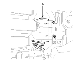
Remove the smart key unit (A)
after disconnecting the connector and loosening the mounting nuts (2EA).
|
| 4. |
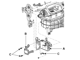
Remove the smart key unit (A)
with bracket (B) after loosening the mounting nuts, shear bolts (C). [CANADA]
|
Do not reuse the shear bolts. When installing the new shear bolts
to the smart key unit, tighten the shear bolts until its head is
cut off. |
|
RF Receiver
| - |
Take care not to scratch
the crash pad and related parts |
|
| 1. |
Disconnect the negative(-) battery
terminal. |
| 2. |
Remove the glove box. (Refer
to the BD group - "Crash pad")
|
| 3. |
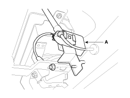
Remove the RF receiver (A) after
loosening the mounting nuts (1EA) and disconnecting the connector.
|
Interior 1 Antenna
| - |
Take care not to scratch
the crash pad and related parts |
|
| 1. |
Disconnect the negative(-) battery
terminal. |
| 2. |
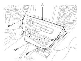
Remove the heater control unit
(A) after removing the screws. (Refer to the BD group - "Crash pad")
|
| 3. |
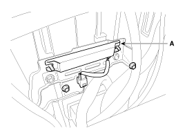
Remove the interior 1 antenna
(A) after disconnecting the connector and loosening the mounting nuts (2EA).
|
Interior 2 Antenna
| 1. |
Disconnect the negative(-) battery
terminal. |
| 2. |
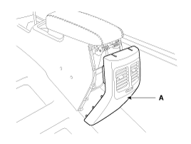
Remove the center console rear
cover (A).
|
Take care not to damage and scratch the console rear cover and its
related parts. Apply the protective tapes to the console rear
cover and its related parts.
|
|
| 3. |
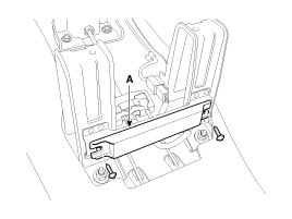
Disconnect the interior 2 antenna
connector located at the console rear side, then remove the interior 2 antenna
(A) after loosening screws (2EA).
|
Trunk Antenna
| 1. |
Disconnect the negative(-) battery
terminal. |
| 2. |
Remove the trunk transverse trim.
(Refer to the BD group - "Interior trim")
|
| 3. |
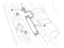
Disconnect the trunk antenna
connector (A) and remove the trunk antenna (B) after loosening nut (2EA).
|
Exterior Bumper Antenna
| 1. |
Disconnect the negative(-) battery
terminal. |
| 2. |
Remove the rear bumper. (Refer
to the BD group - "Rear bumper")
|
| 3. |
Disconnect the antenna connector
(B) and remove the exterior bumper antenna (A) after loosening the screws
(2EA).
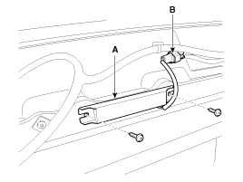
|
Buzzer
| 1. |
Disconnect the negative(-) battery
terminal. |
| 2. |
Remove the left side wheel guard. |
| 3. |
Remove the external buzzer (A)
after disconnecting the connector.
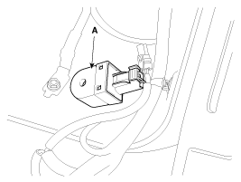
|
Door Outside Handle
| 1. |
Disconnect the negative (-) battery
terminal. |
| 2. |
Remove the front door module.
(Refer to the BD group - "Front door")
|
| 3. |
Remove the hole plug (B). |
| 4. |
After loosening the mounting
bolt, then remove the outside handle cover (A).
Tightening torque:0.7 ~
0.5 N.m (0.07 ~ 0.1 kgf.m, 1.0 ~ 0.7 lb-ft)
|
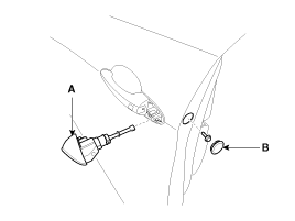
|
| 5. |
Remove the outside handle (A)
by sliding it rearward.
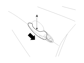
|
| 6. |
Disconnect the outside handle
connector (A).
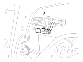
|
Trunk lid open switch
| 1. |
Disconnect the negative(-) battery
terminal. |
| 2. |
Remove the trunk door trim.
(Refer to the BD group - "Trunk")
|
| 3. |
Disconnect the trunk lid open
switch connector (A).
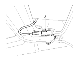
|
| 4. |
Remove the trunk open switch
(A) from the trunk garnish after pressing the clips (B).
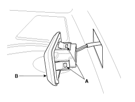
|
Smart Key Unit
-
Refer to the BE group - inspection
/ self diagnosis with GDS.
Smart Key Switch
-
Refer to the BE group - inspection
/ self diagnosis with GDS.
...
Smart Key Unit
1.
Install the smart key unit.
2.
Install the smart key unit mounting
nuts and bolts and connector.
3.
Install the glove box housing.
...
See also:
SRS components and functions
The SRS consists of the following components:
1. Driver's front air bag module 2. Passenger's front air bag module 3. Side
impact air bag modules 4. Curtain air bag modules 5. Retractor p ...
Folding the rear seat
The rear seatbacks may be folded to facilitate carrying long items or to increase
the luggage capacity of the vehicle.
WARNING
The purpose of the fold-down rear seatbacks is to allow you to carry ...
Transaxle Control Module (TCM). Description and Operation
Description
Transaxle Control Module (TCM) is the automatic transaxle's brain. The module receives
and processes signals from various sensors and implements a wide range of transaxle
controls ...
 Kia Optima: Removal
 Inspection
 Installation


