 Kia Optima: Removal
| 1. |
Remove the following items;
| B. |
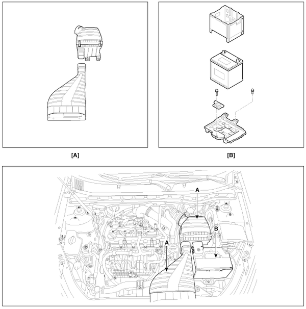
Air cleaner assembly
and air duct (A). (Refer to "Intake and Exhaust system" in EM group.)
|
| C. |
Battery and battery tray
(B). (Refer to "Charging system" in EE group.) |
|
| 2. |
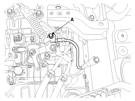
Remove the ground line after
removing the bolt (A).
|
| 3. |
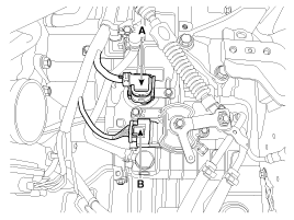
Disconnect the solenoid valve
connector (A) and inhibitor switch connector (B).
|
| 4. |
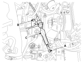
Remove the control cable (C)
after removing the nut (A) and the bolt (B).
Tightening torque:(A) 9.8
~ 14.7 N.m (1.0 ~ 1.5 kgf.m, 7.2 ~ 10.8 lb-ft)
(B) 14.7 ~21.6 N.m(1.5 ~2.2 kgf.m, 10.9 ~15.9 lb-ft)
|
|
| 5. |
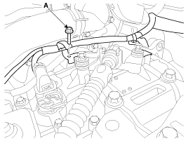
Remove the solenoid valve connector
and inhibitor switch connector wiring mounting bracket (A).
|
| 6. |
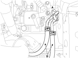
Disconnect the hose (B) after
removing the automatic transaxle fluid cooler hose clamp (A).
|
| 7. |
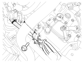
Remove the wiring bracket installation
bolt (A).
|
| 8. |
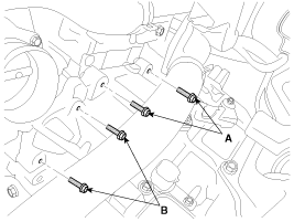
Remove the automatic transaxle
upper mounting bolt (A-2ea) and the starter motor mounting bolt (B-2ea).
Tightening torque:(A),(B):
42.2 ~ 54.0 N.m (4.3 ~5.5 kgf.m, 31.1 ~ 39.8 lb-ft)
|
|
| 9. |
Remove the mounting cover (A).
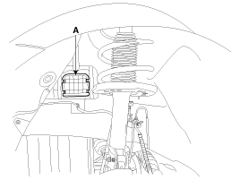
|
| 10. |
Remove the support bracket mounting
bolts (A).
Tightening torque:88.3
~ 107.9 N.m (9.0 ~ 11.0 kgf.m, 65.1 ~ 79.8 lb-ft)
|
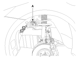
|
| 11. |
Using the engine support fixture
(SST No.: 09200-38001), hold the engine and transaxle assembly safely.
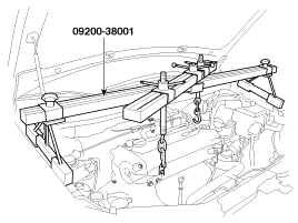
|
| 12. |
Remove the automatic transaxle
mounting support bracket (C).
Tightening torque:(A) 78.5
~ 98.1 N.m (8.0 ~ 10.0 kgf.m, 57.9 ~ 72.3 lb-ft)
(B) 58.9 ~ 78.5 N.m (6.0 ~ 8.0 kgf.m, 43.4 ~ 57.9 lb-ft)
|
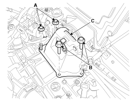
|
| 13. |
Lift the vehicle with a jack.
|
| 14. |
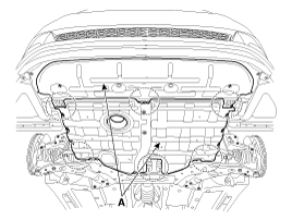
Remove the under cover (A).
Tightening torque:7.8 ~
11.8 N.m (0.8 ~ 1.2 kgf.m, 5.8 ~ 8.7 lb-ft)
|
|
| 15. |
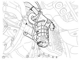
Remove the vaccum pump (A).
|
| 16. |
Remove the following items;
| A. |
Sub frame assembly. (Refer
to "Front suspension system" in SS group.) |
| B. |
Drive shaft assembly.
(Refer to "Drive shaft assembly " in DS group.) |
|
| 17. |
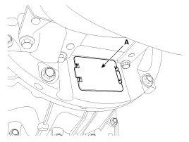
Remove the dust cover (A).
|
| 18. |
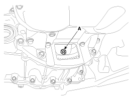
Remove the torque converter mounting
bolt (A-6ea) with rotating the crankshaft.
Tightening torque:45.1
~ 52.0 N.m (4.6 ~ 5.3 kgf.m, 33.3 ~ 38.3 lb-ft)
|
|
| 19. |
Remove the drive shaft cover
mounting bolt (A). |
| 20. |
Remove the automatic transaxle
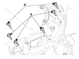
with a jack after removing the mounting bolt (A-4ea, B-2ea).
Tightening torque:(A) 42.2
~ 48.1 N.m (4.3 ~ 4.9 kgf.m, 31.1 ~ 35.4 lb-ft)
(B) 42.2 ~ 54.0 N.m (4.3 ~5.5 kgf.m, 31.1 ~ 39.8 lb-ft)
|
|
1.
Installation is the reverse of
removal.
If the oil seal on the transaxle case side is damaged and fluid is leakin ...
See also:
Power Windows
The ignition switch must be in the ON position for power windows to operate.
Each door has a power window switch that controls that doorŌĆÖs window. However, the
driver has a power window switch w ...
To turn cruise control off, do one of the following
Push the cruise ON/OFF button (the CRUISE indicator light in the instrument
cluster will go off).
Turn the ignition off.
Both of these actions cancel cruise control operation. If you want ...
Components and Components Location
Components
1. Hands free call switch
2. Mic
3. Front left speaker
4. Front right speaker
5. Audio head unit (hands free control)
※ ...
 Kia Optima: Removal
 Installation


