 Kia Optima: Output Speed Sensor. Troubleshooting
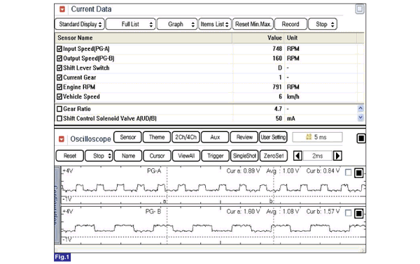
Signal Waveform


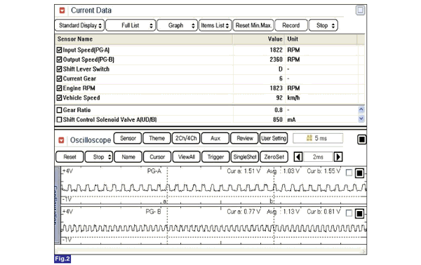
Fig 2) Input/Output speed sensor at high speed
 Output Speed Sensor. Schematic Diagrams
Circuit Diagram
...
See also:
Self Diagnosis
1.
Self-diagnosis process
2.
How to read self-diagnostic code
After the display panel flickers three times every 0.5 second, the corresponding
fault code flick ...
Replacement
1.
Remove the front wheel & tire.
Tightening torque:88.3
~ 107.9N.m(9.0 ~ 11.0kgf.m, 65.1 ~ 79.6lb-ft)
...
Adjustment
1.
After loosening the trunk lid
hinge (A) mounting bolt, adjust the trunk lid by moving it up or down, or
right or left.
2.
Adjust the trunk lid height by
turnin ...
Copyright ® www.kiopman.com 2026

