 Kia Optima: Operation
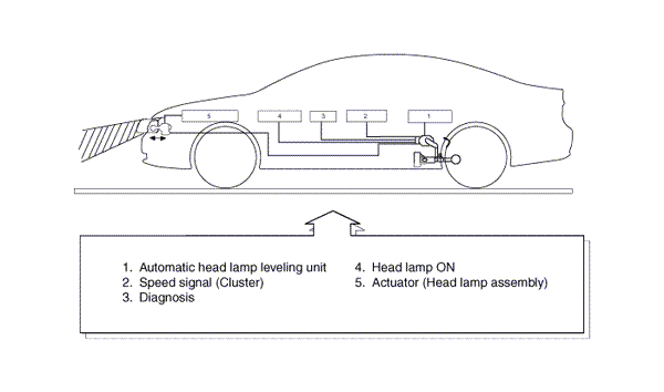
Operating Procedure
| 1. |
Suspension angle change resulted
from vehicle's load change. |
| 3. |
Microprocessor calculates necessary
head lamp angle change amount. |
| 4. |
Sending a proper signal to head
lamp leveling device and driving actuator. |
Operating Condition
| 3. |
On stop : If sensor lever change
is 2┬░ and above, head lamp is operated after max. 1.5 sec. |
| 4. |
On driving : If vehicle velocity
is over 4km/h(2.48mile/h), velocity change is not over 0.8-1.6km/h(0.5 ~
1.0mile/h) per second, and loading condition is changed, then head lamp
is operated. |
Components
| 1. |
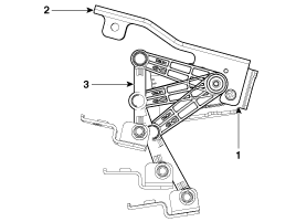
Auto head lamp leveling unit
1. Leveling unit & sensor
2. Sensor mounting bracket3. Sensor linkage

| A. |
Using a Micro-processor,
percept the operation lever's mechanical angle change or speed signal. |
| B. |
As an actuator control
device of inner control program, mounting on the rear center arm. |
|
| 2. |
Actuator
| A. |
Change the head lamp
lighting direction up or down since automatic head lamp leveling
unit sensing the input signal following the vehicle's statically
changes. |
|

According to driving environment and loading state of vehicle, head lamp lighting
direction is changed to keep the driver's visibility range and to protect the driver's
vision from glare, ...
See also:
If you have a flat tire while driving
If a tire goes flat while you are driving:
1.Take your foot off the accelerator pedal
and let the vehicle slow down while
driving straight ahead. Do not apply the
brakes immediately or attempt ...
Disassembly
ŌĆó
Do not disassemble the
BJ assembly.
ŌĆó
Special grease must be
applied to t ...
Parking Brake
ŌĆó To set the parking brake, pull the parking brake handle fully and firmly upward
while applying the service brake.
ŌĆó To release the parking brake, pull the handle up slightly and push the ...
 Kia Optima: Operation
 Description

