 Kia Optima: Front Cross Member. Repair procedures
Replacement
| 1. |
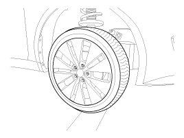
Remove the front wheel & tire.
Tightening torque:88.3
~ 107.9N.m(9.0 ~ 11.0kgf.m, 65.1~79.6lb-ft)
|
|
Be careful not to damage to the hub bolts when removing the front
wheel & tire. |
|
| 2. |
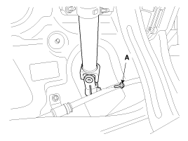
Loosen the bolt (A) and then
disconnect the universal joint assembly from the pinion of the steering
gear box.
Tightening torque:29.4
~ 34.3N.m(3.0 ~ 3.5kgf.m, 21.7 ~ 25.7lb-ft)
|
|
Lock the steering wheel in the straight ahead position to prevent
the damage of the clock spring inner cable when you handle the steering
wheel. |
|
| 3. |
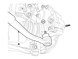
Remove the split pin and castle
nut and then disconnect the tie-rod end (A) from the front knuckle.
Tightening torque:34.3
~ 44.1N.m(3.5 ~ 4.5kgf.m, 25.7 ~ 32.5lb-ft)
|
|
| 4. |
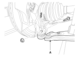
Loosen the bolt & nut and then
remove the lower arm (A).
Tightening torque:98.1
~ 117.7N.m(10.0 ~ 12.0kgf.m, 72.3 ~ 86.8lb-ft)
|
|
| 5. |
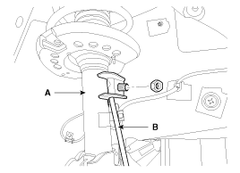
Disconnect the stabilizer link
(B) with the front strut assembly (A) after loosening the nut.
Tightening torque:98.1
~ 117.7N.m(10.0 ~ 12.0kgf.m, 72.3 ~ 86.8lb-ft)
|
|
| 6. |
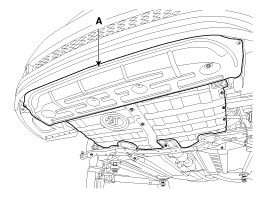
Remove the undercover (A).
|
| 7. |
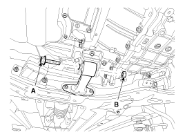
Loosen the bolt (A) & nut (B)
and then remove the roll rod stopper (A).
Tightening torque:107.9
~ 127.5N.m(11.0 ~ 13.0kgf.m, 79.6 ~ 94.0lb-ft)
|
|
| 8. |
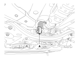
Disconnect the muffler rubber
hanger (A).
|
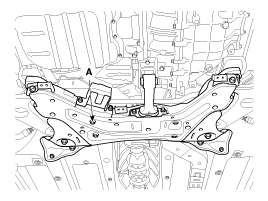
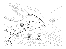
| 9. |
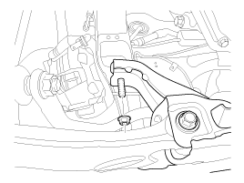
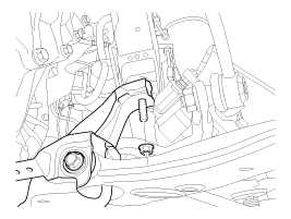
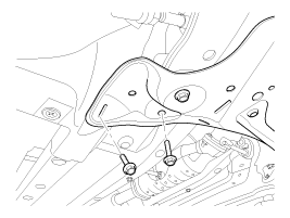
Loosen the bolts & nuts and then
remove the sub frame (A).
Tightening torqueSub frame
mounting bolts & nuts:
156.9 ~ 176.5N.m (16.0 ~ 18.0kgf.m, 115.7 ~ 130.2lb-ft)Sub frame
stay bolts & nuts:
44.1 ~ 58.8N.m (4.5 ~ 6.0kgf.m, 32.5 ~ 43.4lb-ft)
|
|
| 10. |
Remove the front lower arm.
(Refer to Front lower arm)
|
| 11. |
Remove the front stabilizer.
(Refer to Front stabilizer)
|
| 12. |
Remove the steering gearbox.
(Refer to ST group - "Steering Gearbox")
|
| 13. |
Installation is the reverse of
removal. |
1.
Check the bushing for wear and
deterioration.
2.
Check the front stabilizer bar
for deformation.
3.
Check the front stabilizer link
ball joint ...
See also:
To temporarily accelerate with the cruise control on
If you want to speed up temporarily when the cruise control is on, depress the
accelerator pedal. Increased speed will not interfere with the cruise control operation
or change the set speed.
To ...
Cleaning the Upholstery and Interior Trim
Vinyl
Remove dust and loose dirt from vinyl with a whisk broom or vacuum cleaner. Clean
vinyl surfaces with a vinyl cleaner.
Fabric
Remove dust and loose dirt from fabric with a whisk broom or va ...
Operating door locks from outside the vehicle
Turn the key toward the rear of the vehicle to unlock and toward the front
of the vehicle to lock.
If you lock/unlock the door with a key, all vehicle doors will lock/unlock
automatically ...


 Inspection
