 Kia Optima: Console. Repair procedures
Replacement
Floor Console Replacement
| ŌĆó |
When prying with a flat-tip
screwdriver, wrap it with protective tape, and apply protective
tape around the related parts, to prevent damage. |
| ŌĆó |
Put on gloves to protect
your hands. |
|
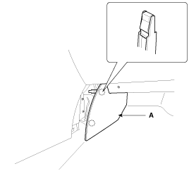
| 1. |
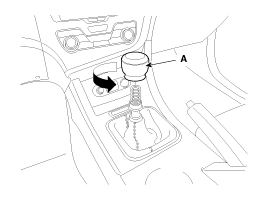
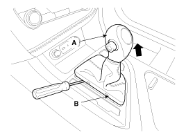
Remove the gear knob (A).
|
| 2. |
Using a screwdriver or remover,
remove the floor console upper cover (A).
|
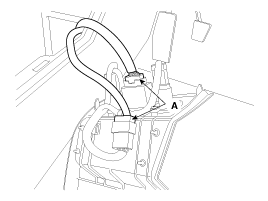
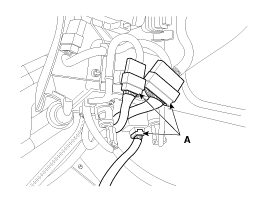
| 3. |
Disconnect the connectors (A).
|
| 4. |
Using a screwdriver or remover,
remove the hand brake cover (A).
|
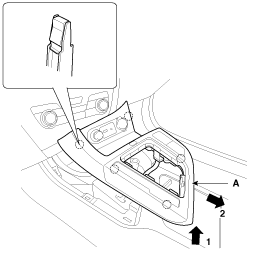
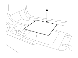
| 5. |
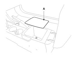
Remove the console tray mat (A).
|
| 6. |
Using a screwdriver or remover,
remove the floor console extension cover (A).
|
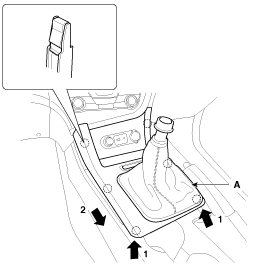
| 7. |
After loosening the mounting
screws and bolts, then remove the floor console assembly (A).
|
| 8. |
Installation is the reverse of
removal.
| ŌĆó
|
Make sure the
connectors are connected in properly. |
| ŌĆó
|
Replace any damaged
clips. |
|
|
| ŌĆó |
When prying with a flat-tip
screwdriver, wrap it with protective tape, and apply protective
tape around the related parts, to prevent damage. |
| ŌĆó |
Put on gloves to protect
your hands. |
|
| 1. |
Using a screwdriver or remover,
remove the gear boots (B) and gear knob (A).
|
| 2. |
Using a screwdriver or remover,
remove the floor console upper cover (A).
|
| 3. |
Disconnect the connectors (A).
|
| 4. |
Remove the console tray mat (A).
|
| 5. |
Using a screwdriver or remover,
remove the floor console extension cover (A).
|
| 6. |
After loosening the mounting
screws and bolts, then remove the floor console assembly (A).
|
| 7. |
Installation is the reverse of
removal.
| ŌĆó
|
Make sure the
connectors are connected in properly. |
| ŌĆó
|
Replace any damaged
clips. |
|
|
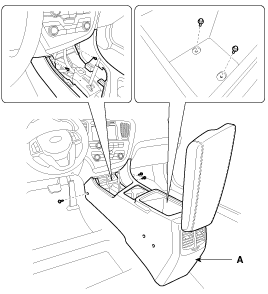
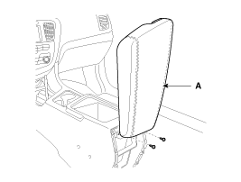
Armrest Replacement
| ŌĆó |
When prying with a flat-tip
screwdriver, wrap it with protective tape, and apply protective
tape around the related parts, to prevent damage. |
| ŌĆó |
Put on gloves to protect
your hands. |
|
| 1. |
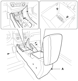
Remove the floor console assembly. |
| 2. |
After loosening the mounting
screws, then remove the rear console cover (A).
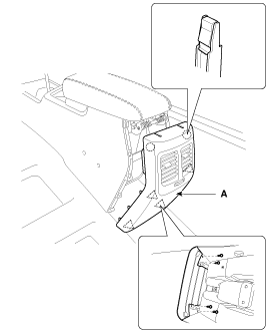
|
| 3. |
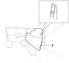
After loosening the mounting
screws, then remove the armrest assembly (A).
|
| 4. |
Installation is the reverse of
removal.
| ŌĆó
|
Replace any damaged
clips. |
|
|
Components
[M/T]
1. Floor console assembly
2. Gear boots
3. Floor console upper cover
4. Floor console extension cover [LH]
5. Floor console extension ...
Components
1. Main crash pad assembly
2. Side speaker grille [LH]
3. Airbag blanking cover
4. Side speaker grille [RH]
5. Center speaker grille
6. Crash pad side cover [ ...
See also:
Steering wheel audio controls
The steering wheel may incorporate audio control buttons.
CAUTION
Do not operate audio remote control buttons simultaneously.
VOLUME ( +/- ) (1)
Press the lever upward ( ) to increase the vo ...
Turbo Charger. Components and Components Location
Components
1. Turbine housing
2. Turbine inlet
3. Turbine outlet
4. Compressor housing
5. Compressor inlet
6. Compressor outlet
7. Center housing
8 ...
Tilting the sunroof
When the sunshade is closed
If you push the sunroof control lever upward, the sunshade will slide all the
way open then the sunroof glass will tilt. To stop the sunroof movement at any point,
p ...
 Console. Components and Components Location
 Crash Pad. Components and Components Location