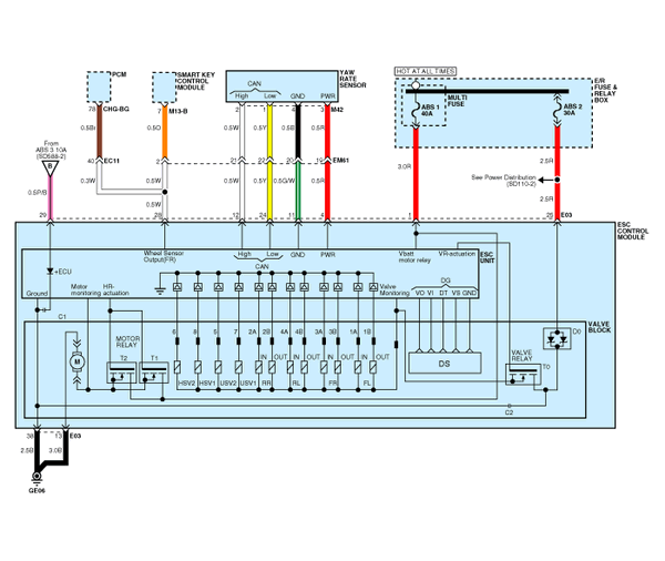
 Kia Optima: Circuit Diagram - ESC (3)

 ESC connector input/output
Connector Terminal
Specification
Remark
No
Description
29
IGNITION1(+)
High level of wake up vol ...
See also:
Repair procedures
Inspection
1.
After disconnecting the vapor hose from the PCV valve,
remove the PCV valve. Visually check for a collapsed vapor hose or hose
leaks.
2.
...
Injector. Specifications
Specification
Item
Specification
Coil Resistance (Ω)
1.25 [20┬░C(68┬░F)]
...
Inspection
1.
Troubleshooting for Speaker
(1)
Basic inspection of speaker
Inspect the sound from speaker after verifying that the speaker
mounting screws are removed and the w ...
Copyright ® www.kiopman.com 2026

