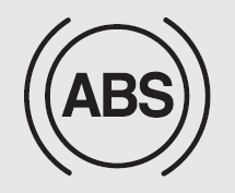
 Kia Optima: Anti-lock brake system (ABS)
![]() WARNING
WARNING
ABS (or ESC) will not prevent accidents due to improper or dangerous driving maneuvers. Even though vehicle control is improved during emergency braking, always maintain a safe distance between you and objects ahead. Vehicle speeds should always be reduced during extreme road conditions. The braking distance for vehicles equipped with an anti-lock braking system (Electronic Stability Control System) may be longer than for those without it in the following road conditions.
During these conditions the vehicle should be driven at reduced speeds:
- Rough, gravel or snow-covered roads.
- On roads where the road surface is pitted or has different surface height.
The safety features of an ABS (or ESC) equipped vehicle should not be tested by high speed driving or cornering. This could endanger the safety of yourself or others.
The ABS continuously senses the speed of the wheels. If the wheels are going to lock, the ABS system repeatedly modulates the hydraulic brake pressure to the wheels.
When you apply your brakes under conditions which may lock the wheels, you may hear a “tik-tik’’ sound from the brakes, or feel a corresponding sensation in the brake pedal. This is normal and it means your ABS is active.
In order to obtain the maximum benefit from your ABS in an emergency situation, do not attempt to modulate your brake pressure and do not try to pump your brakes. Press your brake pedal as hard as possible or as hard as the situation allows the ABS to control the force being delivered to the brakes.
✽ NOTICE
A click sound may be heard in the engine compartment when the vehicle begins to move after the engine is started. These conditions are normal and indicate that the anti-lock brake system is functioning properly.
- Even with the anti-lock brake system, your vehicle still requires sufficient stopping distance. Always maintain a safe distance from the vehicle in front of you.
- Always slow down when cornering. The anti-lock brake system cannot prevent accidents resulting from excessive speeds.
- On loose or uneven road surfaces, operation of the anti-lock brake system may result in a longer stopping distance than for vehicles equipped with a conventional brake system.

![]() CAUTION
CAUTION
- If the ABS warning light is on and stays on, you may have a problem with the ABS. In this case, however, your regular brakes will work normally.
- The ABS warning light will stay on for approximately 3 seconds after the ignition switch is ON. During that time, the ABS will go through self-diagnosis and the light will go off if everything is normal. If the light stays on, you may have a problem with your ABS. Contact an authorized Kia dealer as soon as possible.
- When you drive on a road with poor traction, such as an icy road, and operated your brakes continuously, the ABS will be active continuously and the ABS warning light may illuminate. Pull your vehicle over to a safe place and stop the engine.
- Restart the engine. If the ABS warning light is off, then your ABS system is normal. Otherwise, you may have a problem with the ABS. Contact an authorized Kia dealer as soon as possible.
✽ NOTICE
When you jump start your vehicle because of a drained battery, the engine may not run as smoothly and the ABS warning light may turn on at the same time. This happens because of the low battery voltage. It does not mean your ABS has malfunctioned.
- Do not pump your brakes!
- Have the battery recharged before driving the vehicle.
 Releasing the parking brake
Foot type
To release the parking brake, depress the parking brake pedal a second time while
applying the foot brake. The pedal will automatically extend to the fully released
position.
Hand ...
 ESC (Electronic stability control)
The Electronic Stability control (ESC) system is designed to stabilize the vehicle
during cornering maneuvers. ESC checks where you are steering and where the vehicle
is actually going. ESC appl ...
See also:
Inspection
Smart Key Unit
-
Refer to the BE group - inspection
/ self diagnosis with GDS.
Smart Key Switch
-
Refer to the BE group - inspection
/ self diagnosis with GDS.
...
Rear Window Glass. Components and Components Location
Components
1. Rear window glass molding
2. Rear window glass
...
