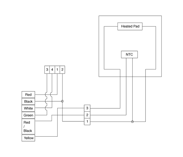
 Kia Optima: System Circuit Diagram

 Connector Terminal Function
1.
Connector terminal
2.
Terminal Function
Housing
Pin
Function
Wire color
...
 Heated Steering wheel. Repair procedures
Inspection
Measure a temperature.
Х
The temperature of wheel surface
grip must rise from -20∞C to 20∞C within 6 minute
Х
The temperature of wheel surface
grip must ...
See also:
Water pump. Components and Components Location
Components
1. Water pump pulley
2. Water pump sub assembly
3. Water pump gasket
4. Water pump cover
5. Water pump cover gasket
6. O-ring
7. Water inle ...
Installation
1.
Installation is reverse of removal.
Accelerator pedal module installation nut:
9.8 ~ 14.7 N.m (1.0 ~ 1.5 kgf.m, 7.2 ~ 10.8
lb-ft)
Accelerator pedal module ...
Fuel Filler Door Open Switch. Repair procedures
Inspection
1.
Remove the driver door trim.
(Refer to the BD group - "Front door")
2.
Remove the switch assembly connector
(A) from the door trim.
...
Copyright © www.kiopman.com 2024
