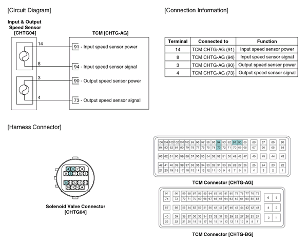
 Kia Optima: Output Speed Sensor. Schematic Diagrams
Circuit Diagram

 Output Speed Sensor. Specifications
Specifications
▷ Type: Hall effect sensor
Operation condition [°C(°F)]
((-)40~150)) -40~302
Air gap(mm)in.
(0.55~1) 0.0217~0.0394
...
 Output Speed Sensor. Troubleshooting
Signal Waveform
Fig 1) Input/Output speed sensor at low speedFig 2) Input/Output speed sensor
at high speed
...
See also:
Components and Components Location
Component Location
1. Start Stop Button(SSB)
2. FOB key holder
3. FOB key
4. Trunk lid open switch
5. Smart key unit
6. RF receiver
7. Body control module
...
Wheel alignment and tire balance
The wheels on your vehicle were
aligned and balanced carefully at the
factory to give you the longest tire life
and best overall performance.
In most cases, you will not need to
have your whe ...
Inspection
1.
Connect the GDS on the Data Link Connector (DLC).
2.
Turn the ignition switch ON.
3.
Measure the output voltage of the APS 1 and 2 at
C.T ...
Copyright © www.kiopman.com 2024
