 Kia Optima: Oil Pump. Components and Components Location
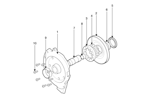
Components

|
1. Reaction shaft support assembly 2. Oil pump housing 3. Driven gear 4. Drive gear 5. Oil seal |
6. Bushing-Housing 7. Reaction shaft 8. Bushing-Reaction shaft 9. Sleeve 10. Bolt |
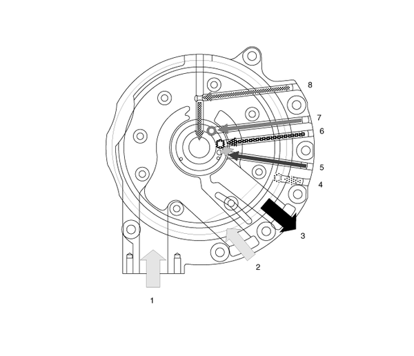
Oil Pump Operation Flow

|
1. Inhale(Oil filter) 2. Inhale(Valve body) 3. Outlet 4. 26/B operation pressure |
5. 35R/C operation pressure 6. Lubrication 7. Line up clutch operation pressure 8. Line up clutch cancellation |
 Oil Pump. Description and Operation
Description
The oil pump is built-in as a single unit with the 26 brake chamber. Rotation of
the pump builds the hydraulic pressure needed for the lubrication of the various
parts of the transaxl ...
 Fluid. Components and Components Location
Components Location
1. Injection hole(eyebolt)
2. Oil level plug
3. Oil drain plug
...
See also:
Removal Of Parts
First find the cause of the problem and then determine whether removal or
disassembly before starting the job.
...
Placing a Passenger Safety Belt Into The Auto Lock Mode
The use of the auto lock mode will ensure that the normal movement of the child
in the vehicle does not cause the safety belt to be pulled out and loosen the firmness
of its hold on the child re ...
Driver's and passenger's front air bag
Driver’s front air bag
Passenger’s front air bag
Your vehicle is equipped with an Advanced Supplemental Restraint (Air Bag) System
and lap/shoulder belts at both the driver and passenger seati ...
Copyright © www.kiopman.com 2024
