 Kia Optima: Function
Function Requirements
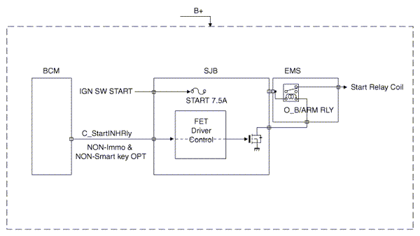
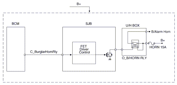
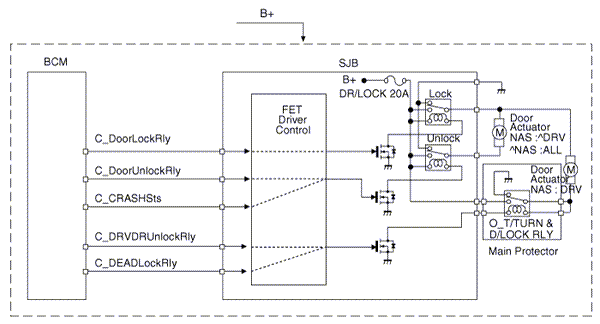
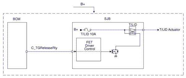
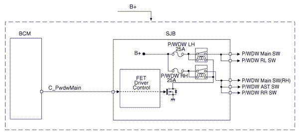
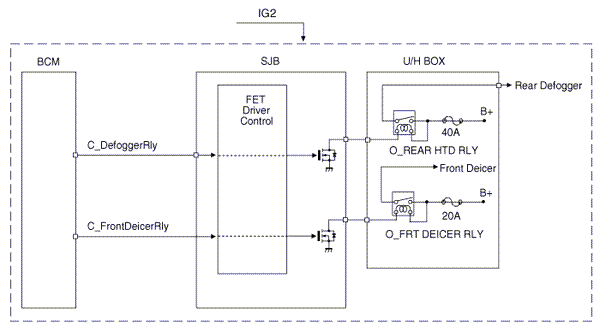
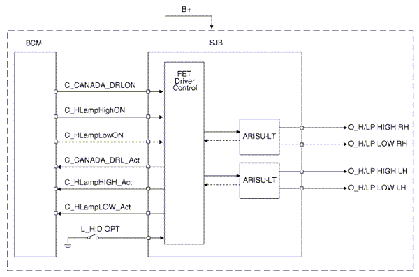
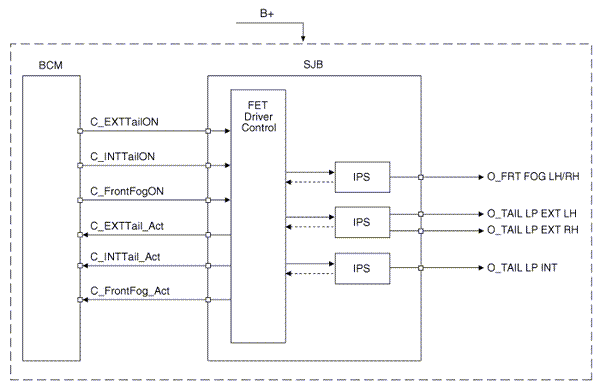
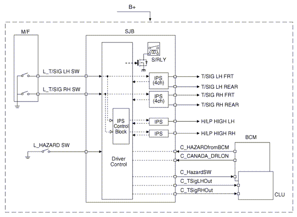
The BCM controls IPS and relay on the SJB. For example, if BCM requests head lamp low beam control, then BCM requests related lamp control at one time.
Signal Flow DiagramThis chapter defines signal between SJB and peripheral electrical apparatus in the form of signal flow diagram. Control of the IPS and relay is required by BCM. Following figure expresses power source that is operating power condition
Input signal|
No |
Switch Input |
|
1 |
IGN1 |
|
2 |
IGN2 |
|
3 |
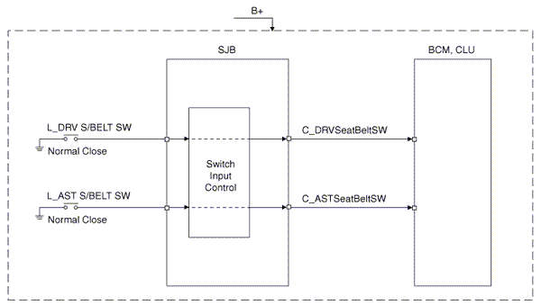
Driver S/Beltelt switch |
|
4 |
Assist S/Beltelt switch |
|
5 |
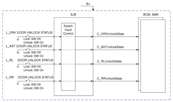
Driver door unlock switch |
|
6 |
Assist door unlock switch |
|
7 |
RL door unlock switch |
|
8 |
RR door unlock switch |
|
9 |
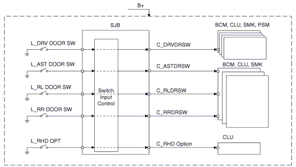
Driver door switch |
|
10 |
Assist door switch |
|
11 |
RL door switch |
|
12 |
RR door switch |
|
13 |
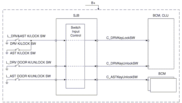
Driver&Assist door key lock |
|
14 |
Driver door key unlock |
|
15 |
Assist door key unlock |
|
16 |
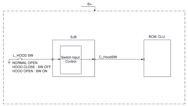
Hood switch |
|
17 |
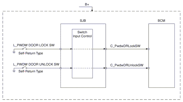
P/W Driver lock switch |
|
18 |
P/W Driver unlock switch |
|
19 |
T/signal LH switch |
|
20 |
T/signal RH switch |
|
21 |
Hazard switch |
|
22 |
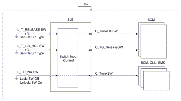
Trunk switch |
|
23 |
Trunk release switch |
|
24 |
Trunk lid HDL switch |
|
25 |
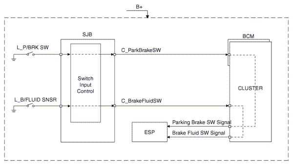
Brake fluid sensor |
|
26 |
Parking brake switch |
|
27 |
Multi function switch |
|
28 |
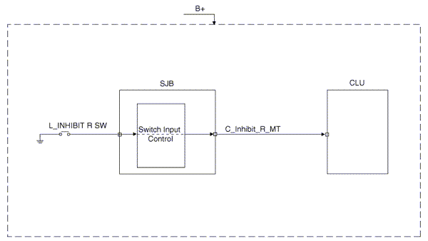
Inhibit ŌĆśRŌĆÖ |
|
29 |
CANADA DRL GND |
|
30 |
HID option |
|
31 |
RHD option |
Output signal
|
No |
Relay Control |
|
1 |
B/Alarm relay |
|
2 |
B/Horn relay |
|
3 |
RR HTD relay |
|
4 |
Driver door unlock relay |
|
5 |
Deicer relay |
|
6 |
Trunk lid relay |
|
7 |
Rear window main relay |
|
8 |
Sound relay |
|
9 |
Door lock relay |
|
10 |
Door unlock relay |
|
No |
IPS Control |
|
1 |
H/Lamp HI LH |
|
2 |
H/Lamp HI RH |
|
3 |
H/Lamp LO LH |
|
4 |
H/Lamp LO RH |
|
5 |
Front fog LP LH/RH |
|
6 |
External Tail lamp LH |
|
7 |
External Tail lamp RH |
|
8 |
T/signal LP FL |
|
9 |
T/signal LP FR |
|
10 |
T/signal LP RL |
|
11 |
T/signal LP RR |
|
12 |
INT Tail lamp LP |
|
13 |
S/Belt LP LH |
|
14 |
S/Belt LP RH |
|
15 |
DRL |
Door Switch Input

 Description
Network ConfigurationThe Network of the SJB(Smart Junction Box) consists of Low
speed CAN as shown in the following figure.
Termination ResistorThe cluster has CAN termination resistor. It is p ...
 Relay Box (Engine Compartment). Repair procedures
Inspection
Power Relay Test (Type A)
-
Do not use pliers.
-
Pliers will damage the
re ...
See also:
Specifications
Specifications
Ignition System
Items
Specifications
Ignition coil
Primary resistance
0.62 ┬▒ 10 % (Ω)
Secondary resi ...
Components and Components Location
Component Location(1)
1. Head lamp (Low)
2. Head lamp (High) / Head lamp (High) & DRL in Canada
3. Turn signal & position lamp
4. Side marker
5. Front fog lamp
...
Washer Switch
...
Categories
Kia Optima Manuals
- Kia Optima DL3 2019-2026 Owners Manual
- Kia Optima DL3 2019-2026 Service and Repair Manual
- Kia Optima TF 2011-{2019} Owners Manual
- Kia Optima TF 2011-2026 Service Manual
- Kia Optima MS/Magentis 2000-2005 Owners Manual
