 Kia Optima: Components and Components Location
Components Location
|
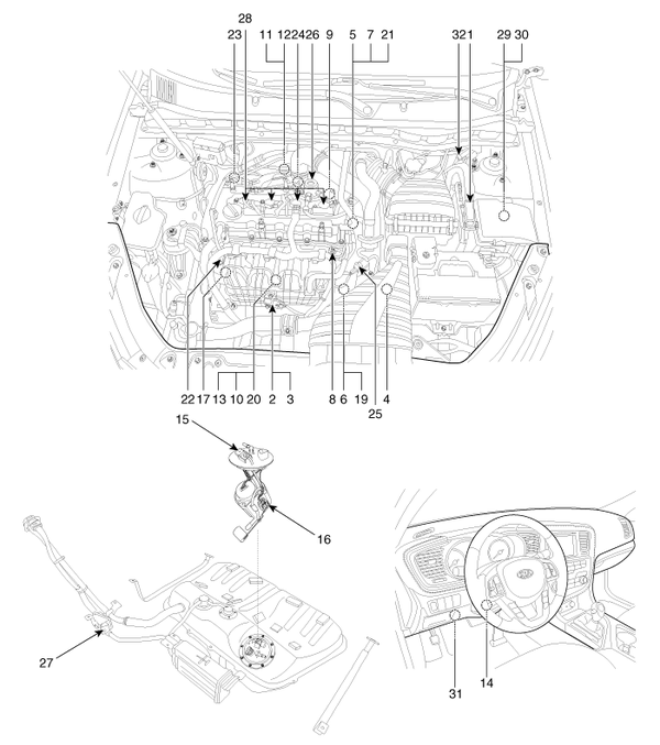
1. Engine Control Module (ECM) 2. Manifold Absolute Pressure Sensor (MAPS) #1 3. Intake Air Temperature Sensor (IATS) 4. Manifold Absolute Pressure Sensor (MAPS) #2 5. Engine Coolant Temperature Sensor (ECTS) 6. Throttle Position Sensor (TPS) [integrated into ETC Module] 7. Crankshaft Position Sensor (CKPS) 8. Camshaft Position Sensor (CMPS) [Bank 1 / Intake] 9. Camshaft Position Sensor (CMPS) [Bank 1 / Exhaust] 10. Knock Sensor (KS) 11. Heated Oxygen Sensor (HO2S) [Bank 1 / Sensor 1] 12. Heated Oxygen Sensor (HO2S) [Bank 1 / Sensor 2] 13. Rail Pressure Sensor (RPS) 14. Accelerator Position Sensor (APS) 15. Fuel Tank Pressure Sensor (FTPS) 16. Fuel Level Sensor (FLS) |
17. CVVT Oil Temperature Sensor (OTS) 18. A/C Pressure Transducer (APT) 19. ETC Motor [integrated into ETC Module] 20. Injector 21. Purge Control Solenoid Valve (PCSV) 22. CVVT Oil Control Valve (OCV) [Bank 1 / Intake] 23. CVVT Oil Control Valve (OCV) [Bank 1 / Exhaust] 24. Electric Waste Gate Actuator (EWGA) 25. RCV Control Solenoid Valve 26. Fuel Pressure Regulator Valve 27. Canister Close Valve (CCV) 28. Ignition Coil 29. Main Relay 30. Fuel Pump Relay 31. Data Link Connector (DLC) [16-Pin] 32. Multi-Purpose Check Connector [20-Pin] |
|
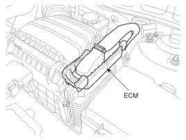
1. Engine Control Module (ECM) |
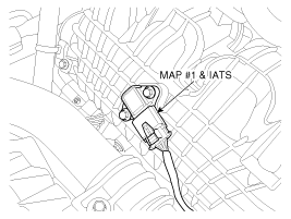
2. Manifold Absolute Pressure Sensor (MAPS) #1 3. Intake Air Temperature Sensor (IATS) |
|
|
|
|
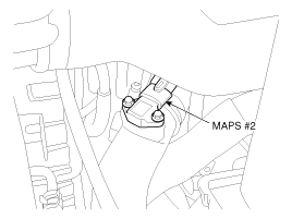
4. Manifold Absolute Pressure Sensor (MAPS) #2 |
5. Engine Coolant Temperature Sensor (ECTS) |
|
|
|
|
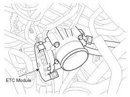
6. Throttle Position Sensor (TPS) 19. ETC Motor |
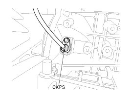
7. Crankshaft Position Sensor (CKPS) |
|
|
|
|
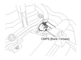
8. Camshaft Position Sensor (CMPS) [Bank 1 / Intake] |
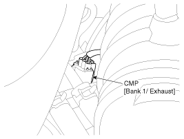
9. Camshaft Position Sensor (CMPS) [Bank 1 / Exhaust] |
|
|
|
|
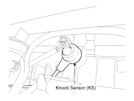
10. Knock Sensor (KS) |
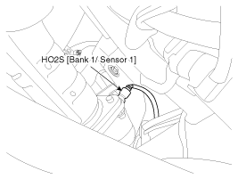
11. Heated Oxygen Sensor (HO2S) [Bank 1/Sensor 1] |
|
|
|
|
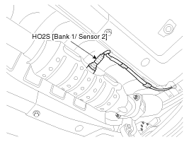
12. Heated Oxygen Sensor (HO2S) [Bank 1/Sensor 2] |
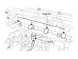
13. Rail Pressure Sensor (RPS) 20. Injector |
|
|
|
|
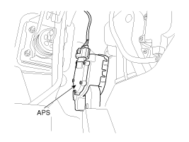
14. Accelerator Position Sensor (APS) |
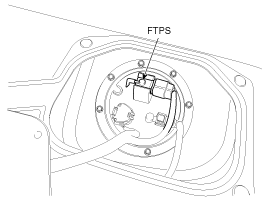
15. Fuel Tank Pressure Sensor (FTPS) |
|
|
|
|
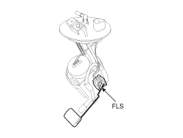
16. Fuel Level Sensor (FLS) |
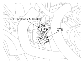
17. CVVT Oil Temperature Sensor (OTS) 22. CVVT Oil Control Valve (OCV) [Bank 1 / Intake] |
|
|
|
|
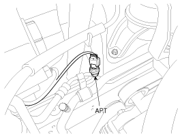
18. A/C Pressure Transducer (APT) |
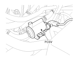
21. Purge Control Solenoid Valve (PCSV) |
|
|
|
|
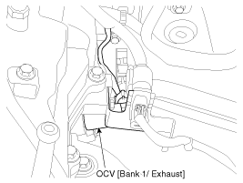
23. CVVT Oil Control Valve (OCV) [Bank 1 / Exhaust] |
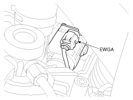
24. Electric Waste Gate Actuator (EWGA) |
|
|
|
|
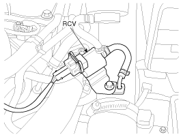
25. RCV Control Solenoid Valve |
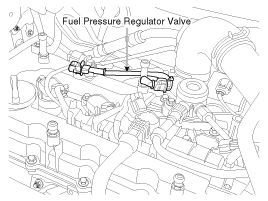
26. Fuel Pressure Regulator Valve |
|
|
|
|
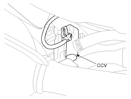
27. Canister Close Valve (CCV) |
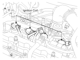
28. Ignition Coil |
|
|
|
|
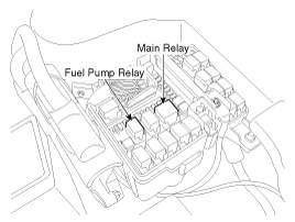
29. Main Relay 30. Fuel Pump Relay |
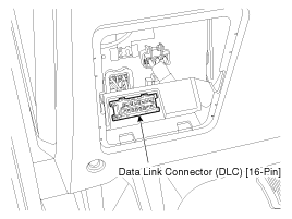
31. Data Link Connector (DLC) [16-Pin] |
|
|
|
|
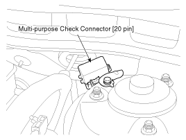
32. Multi-Purpose Check Connector [20-Pin] |
|
|
|

 Description and Operation
OBD-II review
1. OverviewThe California Air Resources Board (CARB) began regulation
of On Board Diagnostics (OBD) for vehicles sold in California beginning with
the 1988 model year. The first ...

See also:
Specifications
Specification
Item
Specification
Ultrasonic sensor
Voltage rating
DC 8.5 V
Detecting range
40 cm ~ 120 cm
...
Starting the engine with an ignition key
1. Make sure the parking brake is applied.
2. Manual Transaxle - Depress the clutch pedal fully and shift the transaxle
into Neutral. Keep the clutch pedal and brake pedal depressed while turning t ...
Categories
Kia Optima Manuals
- Kia Optima DL3 2019-2026 Owners Manual
- Kia Optima DL3 2019-2026 Service and Repair Manual
- Kia Optima TF 2011-{2019} Owners Manual
- Kia Optima TF 2011-2026 Service Manual
- Kia Optima MS/Magentis 2000-2005 Owners Manual

Copyright ® www.kiopman.com 2026