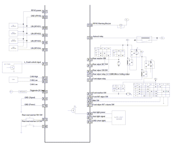
 Kia Optima: Circuit Diagram


 BCM Connector Terminals
BCM Input Signal SPEC
Signal Name
Description
Input Characteristics
(determinant condition
of connector base)
Power
Source
(Pull Up)
...
See also:
Air Flow Control (Mode Switch)
The mode selection button controls the direction of the air flow through the
ventilation system.
The air flow outlet port is same as manual climate control system.
Face position
Air flow is dir ...
Components and Components Location
Components Location
1. AVN (A/V & Navigation head unit)
2. Midrange speaker
3. External amplifier
4. Roof antenna (GPS + SDARS)
5. Front door speaker
6. Rear speak ...
Necessary Inspections
Fluid levels, such as engine oil, engine coolant, brake/clutch fluid, and washer
fluid should be checked on a regular basis, with the exact interval depending on
the fluid. Further details are pro ...
Copyright © www.kiopman.com 2024

