 Kia Optima: Repair procedures
|
If the there is lack of power, excessive oil consumption or poor fuel economy,
measure the compression pressure. |
| 1. |
Warm up and stop engine. Allow
the engine to warm up to normal operating temperature.
|
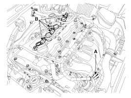
| 2. |
Disconnect the injector extension
connector (A) and ignition coil connectors (B).
|
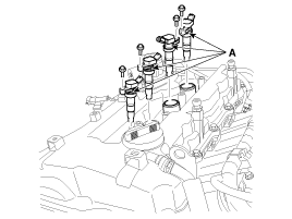
| 3. |
Remove ignition coils (A).
|
| 4. |
Remove spark plugs. Using a
16mm plug wrench, remove the 4 spark plugs.
|
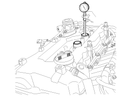
| 5. |
Check cylinder compression pressure.
| (1) |
Insert a compression
gauge into the spark plug hole.
|
| (2) |
Fully open the throttle. |
| (3) |
While cranking the engine,
measure the compression pressure.
|
Always use a fully charged battery to obtain engine speed
of 200 rpm or more. |
|
| (4) |
Repeat steps (1) through
(3) for each cylinder.
|
This measurement must be done in as short a time as possible. |
Compression pressure
:1078 kPa (11.0 kgf/cm², 156 psi) / 200 ~ 250 rpm
Minimum pressure :931 kPa (9.5 kgf/cm², 135 psi)
Difference between each cylinder :100kPa (1.0kgf/cm²,
15psi) or less
|
|
| (5) |
If the cylinder compression
in 1 or more cylinders is low, pour a small amount of engine oil
into the cylinder through the spark plug hole and repeat steps (1)
through (3) for cylinders with low compression.
| A. |
If adding oil
helps the compression, it is likely that the piston rings
and/or cylinder bore are worn or damaged. |
| B. |
If pressure stays
low, a valve may be sticking or seating is improper, or
there may be leakage past the gasket. |
|
|
| 6. |
Reinstall spark plugs. |
| 7. |
Install ignition coils. |
| 8. |
Connect the injector extension
connector and ignition coil connectors. |
| 9. |
Some DTC's may exist after the
inspection test and may need to be manually cleared with GDS. |
Valve Clearance Inspection And Adjustment
|
Inspect and adjust the valve clearance when the engine is cold (Engine coolant
temperature : 20┬░C (68┬░F)) and cylinder head is installed on the cylinder
block. |
|
In case of removing the high pressure fuel pump, high pressure fuel pipe,
delivery pipe, and injector, there may be injury caused by leakage of the
high pressure fuel. So donŌĆÖt do any repair work right after engine stops. |
| 1. |
Remove the cylinder head cover.
(Refer to Timing system in this group) |
| 2. |
Set No.1 cylinder to TDC/compression.
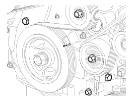
| (1) |
Turn the crankshaft pulley
and align its groove with the timing mark "T" of the lower timing
chain cover.
|
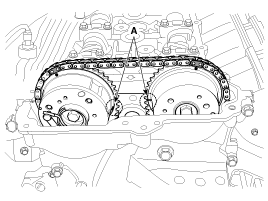
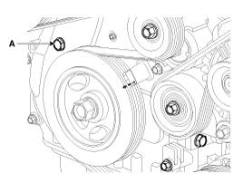
| (2) |
Check that the TDC marks
(A) of the CVVT sprockets are in straight line on the cylinder head
surface as shown in the illustration. If not, turn the crankshaft
one revolution (360┬░)
|
|
| 3. |
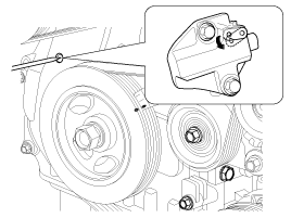
Inspect the valve clearance.
| (1) |
Check only the valve
indicated as shown. Measure the valve clearance.
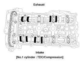
| A. |
Using a thickness
gauge, measure the clearance between the tappet and the
base circle of camshaft. |
| B. |
Record the out-of-specification
valve clearance measurements. They will be used later to
determine the required replacement adjusting tappet. |
Valve clearance
Specification
Engine coolant temperature : 20┬░C [68┬░F]Limit
Intake : 0.10 ~ 0.30mm (0.0039 ~ 0.0118in.)Exhaust :
0.20 ~ 0.40mm (0.0079 ~ 0.0157in.)
|
|
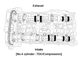
| (2) |
Turn the crankshaft pulley
one revolution (360┬░) and align the groove with timing mark "T"
of the lower timing chain cover. |
| (3) |
Check only valves indicated
as shown. Measure the valve clearance.
|
|
| 4. |
Adjust the intake and exhaust
valve clearance.
| (1) |
Set the No.1 cylinder
to the TDC/compression. |
| (2) |
Mark the timing chains
(A) on the timing marks of the CVVT sprockets.
|
| (3) |
Remove the front camshaft
bearing cap. |
| (4) |
Turn the crankshaft pulley
15┬░ clockwise. |
| (5) |
Remove the service hole
bolt(A) of the timing chain cover.
|
The bolt must not be reused once it has been assembled. |
|
| (6) |
Remove the intake and
exhaust camshaft bearing caps. |
| (7) |
Release the ratchet of
the timing chain tensioner by pulling the link down using a thin
rod.
|
| (8) |
After loosening the timing
chain, remove the exhaust CVVT & camshaft assembly (A) and then
the intake CVVT & camshaft assembly (B).
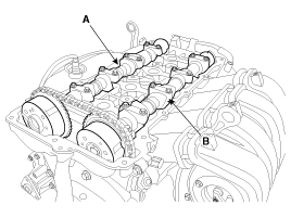
|
When disconnect the timing chain from the CVVT sprocket,
hold the timing chain. |
|
| (9) |
Tie down timing chain
so that it doesn't move.
|
Be careful not to drop anything inside timing chain cover. |
|
| (10) |
Measure the thickness
of the removed tappet using a micrometer.
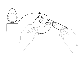
|
| (11) |
Calculate the thickness
of a new tappet so that the valve clearance comes within the specified
value.
Valve clearance [Engine
coolant temperature : 20┬░C(68┬░F)]T : Thickness of removed
tappet
A : Measured valve clearanceN : Thickness of new tappet
Intake : N = T + [A - 0.20mm (0.0079in.)]Exhaust : N
= T + [A - 0.30mm (0.0118in.)]
|
|
| (12) |
Select a new tappet with
a thickness as close as possible to the calculated value.
|
Shims are available in 47 size increments of 0.015mm (0.0006in.)
from 3.00mm (0.118in.) to 3.690mm (0.1452in.) |
|
| (13) |
Place a new tappet on
the cylinder head. |
| (14) |
Hold the timing chain,
and place the intake CVVT & camshaft assembly. |
| (15) |
Place the exhaust CVVT
& camshaft assembly after releasing the ratchet of the timing chain
tensioner.
|
The timing marks of each CVVT sprocket should be matched
with timing marks (painted link) of timing chain when installing
the timing chain. |
|
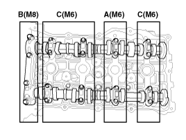
| (16) |
Install the camshaft
bearing caps in their proper locations. Tightening order
Group A → Group B → Group C
Tightening torque
Step 1
M6 : 5.9N.m (0.6kgf.m, 4.3lb-ft)M8 : 14.7N.m (1.5kgf.m,
10.8lb-ft)
Step 2M6 : 10.8 ~ 12.7N.m (1.1 ~ 1.3kgf.m, 8.0 ~ 9.4lb-ft)
M8 : 27.5 ~ 31.4N.m (2.8 ~ 3.2kgf.m, 20.3 ~ 23.1lb-ft)
|
|
| (17) |
Install the service hole
bolt (A).
Tightening torque
:11.8 ~ 14.7N.m (1.2 ~ 1.5kgf.m, 8.7 ~ 10.8lb-ft)
|
|
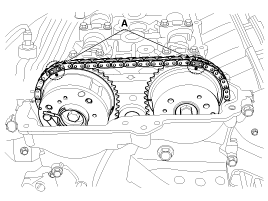
| (18) |
Turn the crankshaft two
turns in the operating direction (clockwise), and then check that
the TDC marks (A) of the CVVT sprockets are in straight line on
the cylinder head surface.
|
| (19) |
Recheck the valve clearance.
Valve clearance [Engine
coolant temperature : 20┬░C(68┬░F)][Specification]
Intake : 0.17 ~ 0.23mm (0.0067 ~ 0.0090in.)Exhaust :
0.32 ~ 0.38mm (0.0126 ~ 0.0150 in.)
|
|
| (20) |
Install the cylinder
head cover. (Refer to Timing system in this group) |
|
Description
Specifications
Limit
General
Type
In-line, DOHC
Number of cylinders
...
Symption
Suspect area
Remedy
Engine misfire with abnormal internal lower engine noises.
Worn crankshaft bearings
Loose or out of s ...
 Specifications
 Troubleshooting