 Kia Optima: Power Door Lock Actuators. Repair procedures
Inspection
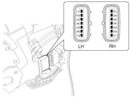
Front Door Lock Actuator Inspection| 1. | Remove the front door trim. (Refer to the BD group - "Front door") |
| 2. | Remove the front door module. |
| 3. | Disconnect the 7P connector from
the actuator.
|
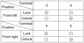
| 4. | Check actuator operation by connecting
power and ground according to the table. To prevent damage to the actuator,
apply battery voltage only momentarily.
|
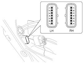
| 1. | Remove the rear door trim. (Refer to the BD group - "Rear door") |
| 2. | Remove the rear door module. |
| 3. | Disconnect the 7P connector from
the actuator.
|
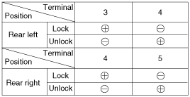
| 4. | Check actuator operation by connecting
power and ground according to the table. To prevent damage to the actuator,
apply battery voltage only momentarily.
|
| 1. | Remove the trunk lid trim panel. (Refer to the BD group - "Trunk lid") |
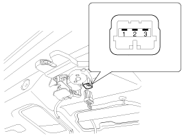
| 2. | Disconnect the 3P connector from
the actuator.
|
| 3. | Check actuator operation by connecting
power and ground according to the table. To prevent damage to the actuator,
apply battery voltage only momentarily.
|
| 1. | Remove the front door trim panel. (Refer to the BD group - "Front door") |
| 2. | Remove the front door module. |
| 3. | Disconnect the 7P connector from
the actuator.
|
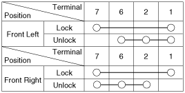
| 4. | Check for continuity between
the terminals in each switch position when inserting the key into the door
according to the table.
|
| 1. | Remove the rear door trim panel. (Refer to the BD group - "Rear door") |
| 2. | Remove the rear door module. |
| 3. | Disconnect the 7P connector from
the actuator.
|
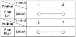
| 4. | Check for continuity between
the terminals in each switch position according to the table.
|
| 1. | Remove the trunk lid trim. (Refer to the BD group - "Trunk lid") |
| 2. | Disconnect the 3P connector from
the actuator.
|
| 3. | Check for continuity between
the terminals in each switch position according to the table.
|
 Components and Components Location
Component Location
1. Driver power window switch
2. Door lock switch
3. BCM (Body Control Module)
4. Front door lock actuator
5. Rear door lock actuator
6. Tru ...
 Power Door Lock Relay. Repair procedures
Inspection
Diagnosis With GDS
1.
It will be able to diagnose defects
of power door lock with GDS quickly. GDS can operates actuator forcefully,
input/output value monitoring and self ...
See also:
Care of seat belts
Seat belt systems should never be disassembled or modified. In addition, care
should be taken to assure that seat belts and belt hardware are not damaged by seat
hinges, doors or other abuse.
WA ...
Inspection
1.
Check each part for cracks, damage
or wear, and replace the coolant pump assembly if necessary.
2.
Check the bearing for damage,
abnormal noise and sluggish rotat ...
OFF mode
Press the OFF button to turn off the air climate control system. However you
can still operate the mode and air intake buttons as long as the ignition switch
is in the ON position. ...

