 Kia Optima: Intake Manifold. Repair procedures
Removal and Installation
| 1. |
Remove the engine cover. |
| 2. |
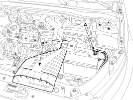
Disconnect the battery negative
terminal (A).
Tightening torque4.0 ~
6.0N.m (0.4 ~ 0.6kgf.m, 3.0 ~ 4.4lb-ft)
|
|
| 3. |
Remove the air duct (B).
|
| 4. |
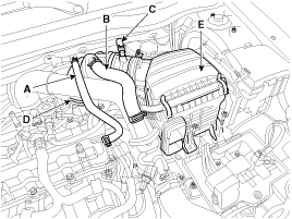
Remove the air cleaner assembly.
| (1) |
Disconnect the breather
hose (A), the recirculation hose (B) and brake booster vacuum hose
(C). |
| (2) |
Disconnect the air intake
hose (D) and then remove the air cleaner assembly (E).
Tightening torque
Hose clamp bolt:
2.9 ~ 4.9N.m (0.3 ~ 0.5kgf.m, 2.2 ~ 3.6lb-ft)
Air cleaner assembly bolts:
7.8 ~ 9.8N.m (0.8 ~ 1.0kgf.m, 5.8 ~ 7.2lb-ft)
|
|
|
| 5. |
Remove the under covers. (Refer
to Engine and transaxle assembly in this group) |
| 6. |
Loosen the drain plug, and drain
the engine coolant. Remove the radiator cap to drain with speed. (Refer
to Cooling system in this group) |
| 7. |
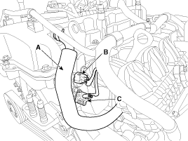
Disconnect the PCV hose (A),
the intake OCV (Oil control valve) connector (B) and the OTS (Oil temperature
sensor) connector (C)
|
| 8. |
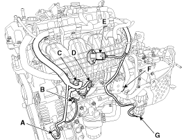
Disconnect the A/C compressor
switch connector (A), the alternator connector (B), the OPS (Oil pressure
switch) connector & injector extension connector (C), the knock sensor connector
(D), the MAPS (Manifold absolute pressure sensor) & IATS (Intake air temperature
sensor) connector (E), the ETC (Electronic throttle control) connector (F)
and the vacuum pump connector (G).
|
| 9. |
Disconnect the throttle body
coolant hoses (A).
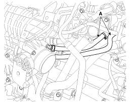
|
| 10. |
Remove the oil level gauge (A).

|
| 11. |
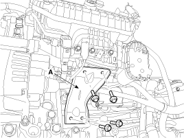
Remove the intake manifold stay
(A).
Tightening torque :18.6
~ 23.5N.m (1.9 ~ 2.4kgf.m, 13.7 ~ 17.4lb-ft)
|
|
| 12. |
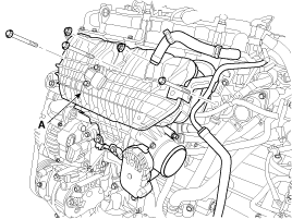
Remove the intake manifold (A)
after disconnecting the vacuum hoses.
Tightening torque :18.6
~ 23.5N.m (1.9 ~ 2.4kgf.m, 13.7 ~ 17.4lb-ft)
|
|
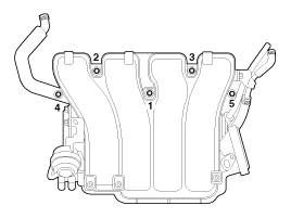
When installing, replace with new gaskets. |
When installing the intake manifold, tighten the bolts and nuts with pre-torque
first, and then tighten the bolts and nuts with specified torque in the
sequence shown.
|
| 13. |
Installation is reverse order
of removal. |
Components
1. Intake manifold assembly
2. Electronic throttle body
3. Intake manifold stay
4. Intake manifold gasket
...
Components
1. Hear protector
2. EWGA(Electric Waste Gate Actuator)
3. C-ring
4. Turbo manifold module
5. Turbocharger stay
6. Trubo adapter gasket
7. Turbo ad ...
See also:
Inspection
1.
Insert a thin stick (A) into the PCV valve (B) from
the threaded side to check that there is the plunger movement.
...
Inspection
1.
Check the hub for cracks and
the splines for wear.
2.
Check the brake disc for scoring
and damage.
3.
Check the rear axle carrier for
cracks.
...
Installing a child restraint on a front passengerŌĆÖs seat is forbidden
Never place a rear-facing child restraint in the front passengerŌĆÖs seat. If the
air bag deploys, it would impact the rear-facing child restraint, causing serious
or fatal injury.
In addition, ...
 Kia Optima: Intake Manifold. Repair procedures
 Intake Manifold. Components and Components Location
 Exhaust Manifold. Components and Components Location


