 Kia Optima: Turbo Charger. Components and Components Location
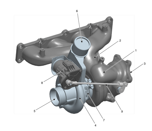
Components
|
1. Turbine housing 2. Turbine inlet 3. Turbine outlet 4. Compressor housing 5. Compressor inlet |
6. Compressor outlet 7. Center housing 8. EWGA (Electric Waste Gate Actuator) 9. Actuator rod |
 Exhaust Manifold. Repair procedures
Removal and Installation
1.
Remove the engine cover.
2.
Disconnect the battery negative
terminal.
Tightening torque4.0 ~
6.0N.m (0.4 ~ 0.6kgf.m, 3.0 ~ ...
 Turbo Charger. Repair procedures
On-vehicle Inspection
Turbocharger Diagnostic Flow
If any problem related with turbocharger, such as lack of engine power, poor acceleration,
abnormal engine noise or oil leaks, ma ...
See also:
Troubleshooting
Basic Troubleshooting
Basic Troubleshooting Guide
Customer Problem Analysis Sheet
Basic Inspection ProcedureMeasuring Condition of Electronic Parts' Resistance
The measured resistance at hi ...
Anchor Pretensioner (APT). Components and Components Location
Components
...
Components (1)
1. Ventilation blower
2. Ventilation ECU
3. Ventilation seat switch
...
Categories
Kia Optima Manuals
- Kia Optima DL3 2019-2026 Owners Manual
- Kia Optima DL3 2019-2026 Service and Repair Manual
- Kia Optima TF 2011-{2019} Owners Manual
- Kia Optima TF 2011-2026 Service Manual
- Kia Optima MS/Magentis 2000-2005 Owners Manual

Copyright ® www.kiopman.com 2026