 Kia Optima: Lighting control
The light switch has a Headlight and a Parking light position.
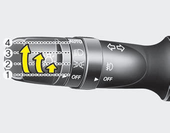
To operate the lights, turn the knob at the end of the control lever to one of the following positions:
(1) OFF position
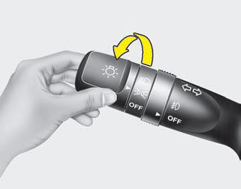
(2) Parking light position
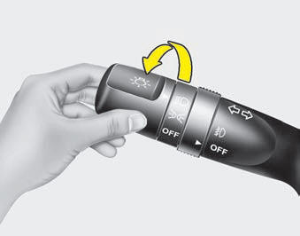
(3) Headlight position
(4)
Auto light position (if equipped)
Parking light position ( )
)
When the light switch is in the parking light position, the tail, license and instrument panel lights will turn ON.
Headlight position ( )
)
When the light switch is in the headlight position, the head, tail, license and instrument panel lights will turn ON.
✽ NOTICE
The ignition switch must be in the ON position to turn on the headlights.
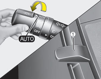
Auto light position (if equipped)
When the light switch is in the AUTO light position, the taillights and headlights will turn ON or OFF automatically depending on the amount of light outside the vehicle.
![]() CAUTION
CAUTION
- Never place anything over sensor (1) located on the instrument panel. This will ensure better auto-light system control.
- DonŌĆÖt clean the sensor using a window cleaner. The cleaner may leave a light film which could interfere with sensor operation.
- If your vehicle has window tint or other types of metallic coating on the front windshield, the Auto light system may not work properly.
 Daytime running light
Daytime Running Lights (DRL) can make it easier for others to see the front of
your vehicle during the day. DRL can be helpful in many different driving conditions,
and it is especially helpful af ...
 High beam operation
To turn on the high beam headlights, push the lever away from you. Pull it back
for low beams.
The high beam indicator will light when the headlight high beams are switched
on.
To prevent the ...
See also:
Battery. Components and Components Location
Components
1. Battery insulation pad
2. Battery
3. Battery tray
4. Battery mounting bracket
...
Owner maintenance schedule
When you stop for fuel:
Check the engine oil level.
Check the coolant level in coolant
reservoir.
Check the windshield washer fluid
level.
Look for low or under-inflated tires.
Whil ...
Seat belt restraint system
WARNING
For maximum restraint system protection, the seat belts must always be
used whenever the vehicle is moving.
Seat belts are most effective when seatbacks are in the upright position.
...
Categories
Kia Optima Manuals
- Kia Optima DL3 2019-2026 Owners Manual
- Kia Optima DL3 2019-2026 Service and Repair Manual
- Kia Optima TF 2011-{2019} Owners Manual
- Kia Optima TF 2011-2026 Service Manual
- Kia Optima MS/Magentis 2000-2005 Owners Manual
