 Kia Optima: ESC connector input/output
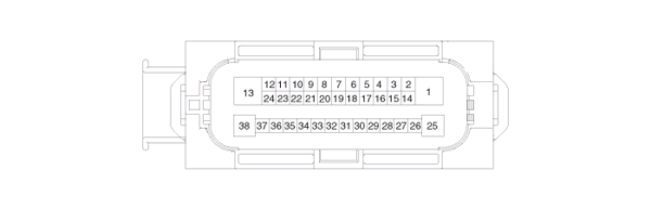
|
Connector Terminal |
Specification |
Remark |
|
|
No |
Description |
||
|
29 |
IGNITION1(+) |
High level of wake up voltage : 4.5V < V < 16.0V Low level of wake up voltage : V < 2.4V Max. current : I < 50mA |
|
|
25 |
POS. BATTERY 1.(SOLENOID) |
Over voltage range : 17.0 ┬▒ 0.5V Operating voltage range : 10.0 ┬▒ 0.5V < V < 16.0 ┬▒ 0.5V Low voltage range : 7.0 ┬▒ 0.5V < V < 9.5 ┬▒ 0.5V Max. current : I < 40A Max. leakage current : I < 0.25mA |
|
|
1 |
POS. BATTERY 2.(MOTOR) |
Operating voltage range: 10.0 ┬▒ 0.5V < V < 16.0 ┬▒ 0.5V Rush current : I < 110A Max current : I < 40A Max leakage current : I < 0.25mA |
|
|
38 |
GROUND |
Rated current : I <550mA Max. current: I < 40A |
|
|
13 |
PUMP MOTOR GROUND |
Rush current : I < 110A Max current : I < 40A |
|
|
11 |
SENSOR GROUND |
Rated current : I <250mA |
|
|
4 |
SENSOR POWER |
Max current Capability : I < 250mA Max voltage : V_BAT1 -0.8V |
|
|
23 |
BRAKE LIGHT SWITCH |
Input voltage (Low) : V < 2.0V Input voltage (High) : V. 6.0V Max. Input current : I < 3mA (@12.8V) |
|
|
10 |
ESC ON/OFF SWITCH |
||
|
9 |
BRAKE SWITCH |
||
|
35 |
CLUTCH SWITCH (M/T Only) |
Input voltage (Low) : V < 2.0V Input voltage (High) : V. 6.0V Max input current : I < 5mA (@12.8V) |
|
|
28 |
SENSOR FRONT RIGHT OUTPUT |
External pull up resistance :1 KΩ < R Output duty : 50 ┬▒ 20% |
|
|
14 |
CAN BUS LINE(LOW) |
Max. Input current : I < 10mA |
|
|
26 |
CAN BUS LINE(HIGH) |
||
|
18 |
SENSOR FRONT LEFT POWER |
Output voltage : V_BAT1 -0.6V ~ V_BAT1 -1.1V Output current : Max 30mA |
|
|
34 |
SENSOR FRONT RIGHT POWER |
||
|
19 |
SENSOR REAR LEFT POWER |
||
|
33 |
SENSOR REAR RIGHT POWER |
||
|
31 |
SENSOR FRONT LEFT SIGNAL |
Input current LOW : 5.9 ~ 8.4mA Input current HIGH : 11.8 ~ 16.8mA Frequency range : 1 ~ 2,500Hz Input duty : 50 ┬▒ 10% |
|
|
21 |
SENSOR FRONT RIGHT SIGNAL |
||
|
32 |
SENSOR REAR LEFT SIGNAL |
||
|
20 |
SENSOR REAR RIGHT SIGNAL |
||
|
12 |
CAN SENSOR LINE (HIGH) |
Max. input current : I < 10mA |
|
|
24 |
CAN SENSOR LINE (LOW) |
||
|
8 |
BRAKE RELAY |
Max. current : I < 180mA Max. Output low voltage : V <1.2V |
|
|
36 |
RELAY STATE MONITORING |
Input voltage (Low) : V < 2V Input voltage (High) : V. 6V Max. Input current : I < 10mA |
|

 Troubleshooting
Failure Diagnosis
1.
In principle, ESC and TCS controls
are prohibited in case of ABS failure.
2.
When ESC or TCS fails, only the
failed system control is prohibited ...
See also:
Folding the rear seat
The rear seatbacks may be folded to facilitate carrying long items or to increase
the luggage capacity of the vehicle.
WARNING
The purpose of the fold-down rear seatbacks is to allow you to carry ...
Front Fog Light Replacement
1. Turn the bulb socket counter- clockwise and remove the bulb socket.
2. Insert a new bulb in socket.
3. Install the bulb socket. ...
Owner maintenance schedule
When you stop for fuel:
Check the engine oil level.
Check the coolant level in coolant
reservoir.
Check the windshield washer fluid
level.
Look for low or under-inflated tires.
Whil ...
Categories
Kia Optima Manuals
- Kia Optima DL3 2019-2026 Owners Manual
- Kia Optima DL3 2019-2026 Service and Repair Manual
- Kia Optima TF 2011-{2019} Owners Manual
- Kia Optima TF 2011-2026 Service Manual
- Kia Optima MS/Magentis 2000-2005 Owners Manual

Copyright ® www.kiopman.com 2026