 Kia Optima: Removal
| 1. |
Remove the battery and the battery
tray. (Refer to "Charging system" in EE group.) |
| 2. |
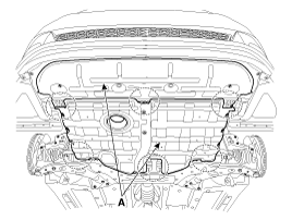
Remove the under cover (A).
Tightening torque:7.8 ~
11.8 N.m (0.8 ~ 1.2 kgf.m, 5.8 ~ 8.7 lb-ft)
|

|
| 3. |
Replace new gasket and the plug
after draining the automatic transaxle fluid by removing the drain plug.
(Refer to "Hydraulic system (Fluid)" in this group) |
| 4. |
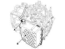
Remove the valve body cover (B)
and eyebolt (A).
Tightening torque:(A) 34.3
~ 44.1 N.m (3.5 ~ 4.5 kgf.m, 25.3 ~ 32.6 lb-ft)
(B) 13.8 ~ 14.7 N.m (1.3 ~ 1.5 kgf.m, 9.4 ~ 10.8 lb-ft)
|
|
Always replace the gasket of the eyebolt use new one whenever loosening
eyebolt. |
|
Remove installation bolts in the engine compartmentfirst and then
remove others under the vehicle. |

|
| 5. |
Remove the plate and the detent
spring (A) after removing the bolt.
Tightening torque:24.5
~ 35.3 N.m (2.5 ~ 3.6 kgf.m, 18.1 ~ 26.0 lb-ft)
|

|
| 6. |
Remove the bolt (3ea) after disconnecting
the solenoid valve connector (A) and the oil temperature sensor connector
(B).
Tightening torque:9.8 ~
11.8 N.m (1.0 ~ 1.2 kgf.m, 7.2 ~ 8.7 lb-ft)
|
|
Be careful not to damage the harness lock connector. |

|
| 7. |
Remove the valve body assembly
(A).
Tightening torque:9.8 ~
11.8 N.m (1.0 ~ 1.2 kgf.m, 7.2 ~ 8.7 lb-ft)
|

|
| 8. |
Disconnect the input & output
speed sensor connector(A). |
| 9. |
Remove the input & output speed
sensor (B) after removing the bolts(2ea).
Tightening torque:9.8 ~
11.8 N.m (1.0 ~ 1.2 kgf.m, 7.2 ~ 8.7 lb-ft)
|

|
1.
Check signal waveform of Input
& output speed sensor using the GDS.
Specification: Refer to "Signal
Wave Form" section.
...
1.
Installation is the reverse of
removal.
After replacement or reinstallation procedure of the valve body assembly, ...
See also:
Erasing Programmed Buttons
To erase the three HomeLink buttons, press and hold the two outside buttons until
the indicator light begins to flash (after 20 seconds). Release both buttons.
Individual buttons cannot be erased ...
Compressor Oil. Repair procedures
Oil Specification
1.
The HFC-134a system requires
synthetic (PAG) compressor oil whereas the R-12 system requires mineral
compressor oil. The two oils must never be mixed.
...
Power Out Side Mirror Switch. Repair procedures
Inspection
1.
Disconnect the negative (-) battery
terminal.
2.
Remove the front door trim panel.
(Refer to the BD group - "Front door")
3.
...
 Kia Optima: Removal
 Inspection
 Installation


