 Kia Optima: Fluid. Components and Components Location
Components Location
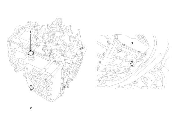
|
1. Injection hole(eyebolt) 2. Oil level plug 3. Oil drain plug |
 Oil Pump. Components and Components Location
Components
1. Reaction shaft support assembly
2. Oil pump housing
3. Driven gear
4. Drive gear
5. Oil seal
6. Bushing-Housing
7. Reaction shaft
8. Bushin ...

See also:
Master Cylinder. Components and Components Location
Components
1. Reservoir cap
2. Reservoir
3. Grommet
4. Master cylinder
...
Air Bag Warning
This warning light will
remain on for approximately 6 seconds each time you turn the ignition switch ON.
If the system does not operate as described or if the light comes on while the vehicle
is ...
Schematic Diagrams
Schematic Diagram
CanisterThe Canister is filled with charcoal and absorbs evaporated
fuel vapor from the fuel tank. The gathered fuel vapor in canister is drawn
into the intake manifold b ...
Copyright © www.kiopman.com 2024