 Kia Optima: Components and Components Location
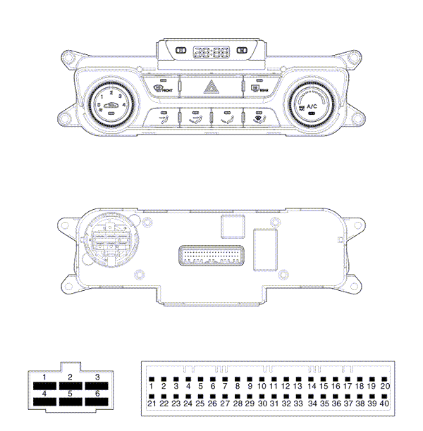
Components
|
Connector |
PIN NO. |
Function |
Connector |
PIN No. |
Function |
|
Connector(A) |
1 |
GND |
Connector(B) |
18 |
Hazard Signal |
|
2 |
Middle High |
19 |
- |
||
|
3 |
Middle Low |
20 |
Rheostat (ILL -) |
||
|
4 |
High |
21 |
IGN2 |
||
|
5 |
Common |
22 |
IGN1 |
||
|
6 |
Low |
23 |
ACC |
||
|
Connector(B) |
1 |
BAttery |
24 |
- |
|
|
2 |
Tail Lamp (ILL+) |
25 |
- |
||
|
3 |
Sensor REF (+5V) |
26 |
Rear Defog S/W |
||
|
4 |
Mode Actuator (F/B) |
27 |
- |
||
|
5 |
Temp Actuator (F/B) |
28 |
- |
||
|
6 |
Intake Actuator (F/B) |
29 |
Detent Out (+) |
||
|
7 |
Evaporator Sensor (+) |
30 |
Blower F/B |
||
|
8 |
Ambient Sensor (+) |
31 |
Sensor GND |
||
|
9 |
- |
32 |
- |
||
|
10 |
Blower Common |
33 |
C – Can HIGH |
||
|
11 |
HTD |
34 |
C – Can LOW |
||
|
12 |
Mode Actuator (VENT) |
35 |
ECV + |
||
|
13 |
Mode Actuator (DEF) |
36 |
ECV – (GND) |
||
|
14 |
Temp Actuator (COOL) |
37 |
- |
||
|
15 |
Temp Actuator (WARM) |
38 |
Sensor GND |
||
|
16 |
Intake Actuator (FRE) |
39 |
GND |
||
|
17 |
Intake Actuator (REC) |
40 |
GND |

 Heater & A/C Control Unit(Manual). Repair procedures
Replacement
1.
Disconnect the negative (-) battery
terminal.
2.
Using the screwdriver, remove
the side cover (A).
3.
Loosen the mounting scre ...
See also:
Component (1)
Connector Pin Information
No
Connector A (14P)
No
Connector B (26P)
1
GND 1
1
-
15
...
To set cruise control speed
1. Press the CRUISE ON-OFF button on the steering wheel to turn the system on.
The CRUISE indicator light in the instrument cluster will illuminate.
2. Accelerate to the desired speed, which must ...
Side Impact Sensor (SIS). Description and Operation
Description
Side Impact Sensor (SIS) system consists of two P-SIS which are installed at each
center of the front door module (LH and RH) and two SIS which are installed at each
center pillar nea ...
Copyright © www.kiopman.com 2024